SKU: IOWC-1025
📋 GST Invoice Available

UByte S32K312 SmartWheels Micro EV2 Automotive Dev Board w/ Segger & IMU

₹4,899.00 (Inclusive of all taxes)
Out of Stock

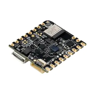
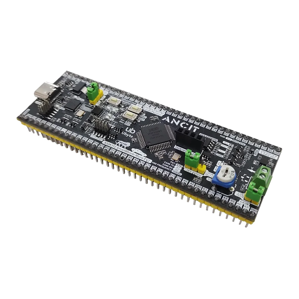
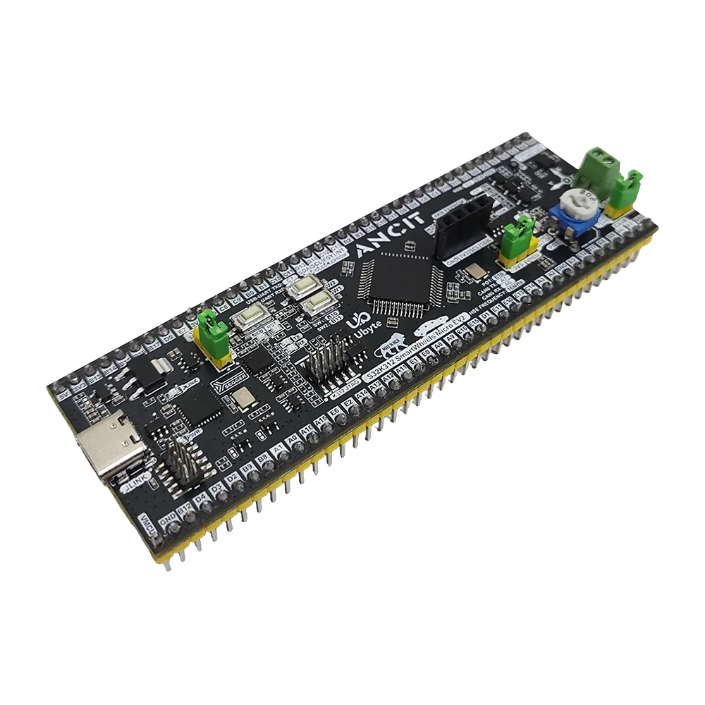
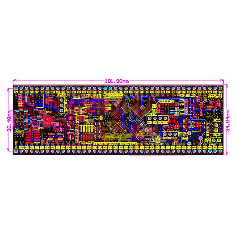
The UByte S32K312 SmartWheels Micro EV2 is an automotive-grade development board featuring an NXP Semiconductors S32K312 Cortex-M7 MCU, integrated Segger Segger debugger, 6-axis IMU, and CAN FD transceiver, designed for prototyping ASIL-B compliant automotive applications.

Features

  • NXP Semiconductors S32K312 Automotive MCU: ARM Cortex-M7 core running at 120MHz with ISO 26262 ASIL-B functional safety compliance.
  • Integrated Debugging: Onboard Segger Segger debugger with USB Type-C connection for seamless programming and power.
  • Automotive Connectivity: Built-in CAN FD transceiver (CAN 2.0B) for robust in-vehicle network communication.
  • Motion Sensing: Includes ICM‑42670‑P 6‑axis IMU sensor for advanced motion detection and telemetry.
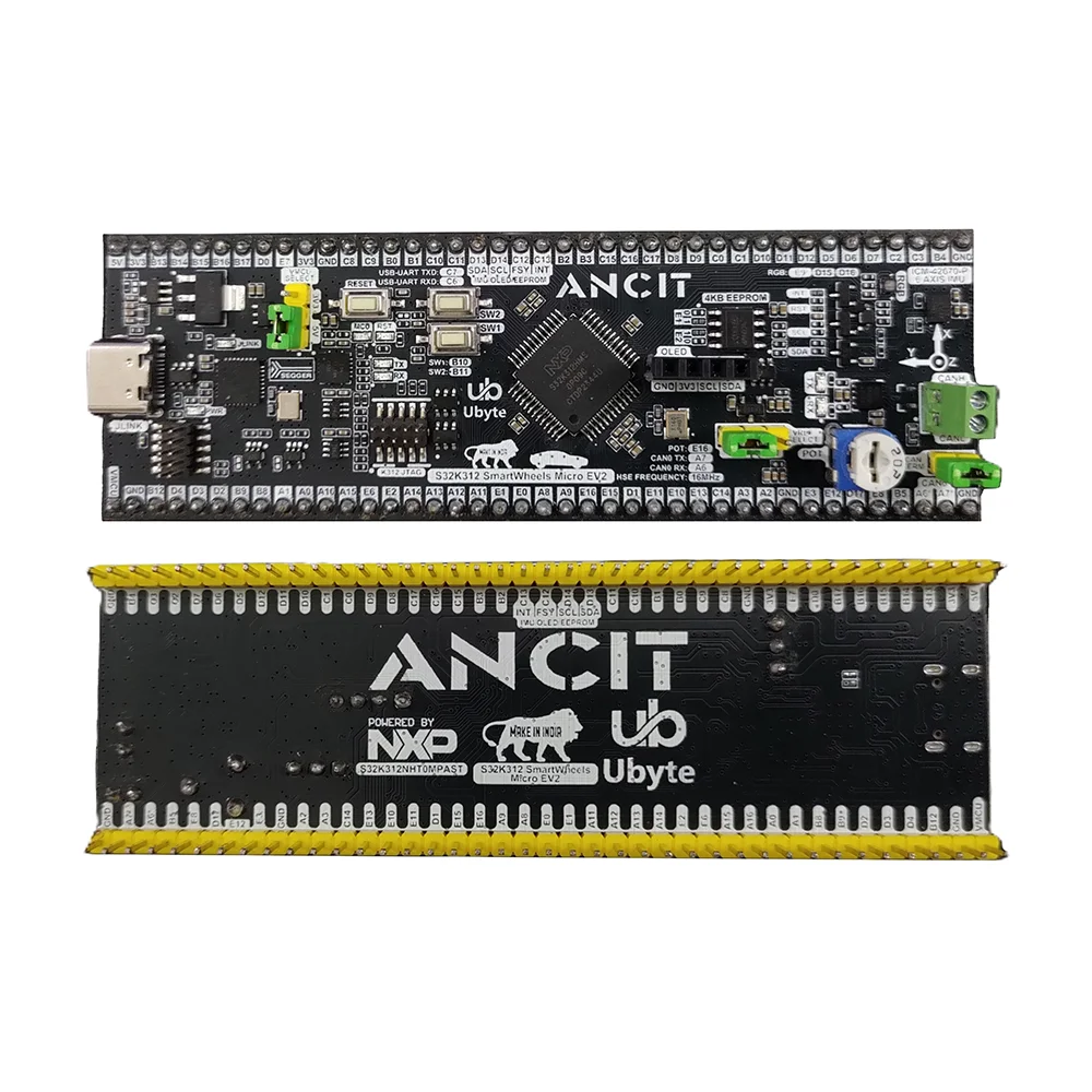
  • Prototyping Flexibility: Breadboard-compatible form factor with 71 GPIOs, switchable logic/ADC voltage (3.3V/5V), and onboard EEPROM.

Out of stock

Description

The S32K312 SmartWheels Micro EV2 is a comprehensive automotive development platform centered on the NXP Semiconductors S32K312NHT0VPASR microcontroller. This Cortex-M7 based MCU operates at 120MHz and is engineered for functional safety, meeting ISO 26262 standards up to ASIL B. The board integrates critical automotive peripherals directly, including a CAN FD transceiver for vehicle bus communication and a high-precision 6-axis IMU for motion sensing, making it an ideal single-board solution for developing advanced driver-assistance systems (ADAS), body control modules, and telematics units.

Designed for rapid prototyping, the board features a breadboard-compatible footprint exposing 71 GPIOs for extensive peripheral connection. It offers flexible power and signal conditioning with user-selectable logic levels (3.3V or 5V) and a switchable ADC reference voltage. The integrated Segger Segger debugger simplifies firmware development and flashing via a single USB Type-C port, while the included 1.3-inch OLED display facilitates immediate visual feedback for sensor data and system status.

Key Features

  • ASIL-B Automotive MCU: NXP Semiconductors S32K312 Cortex-M7 processor certified for ISO 26262 functional safety applications.
  • Onboard Debug Probe: Integrated Segger Segger provides out-of-the-box programming and debugging via USB-C.
  • CAN FD Communication: Built-in CAN 2.0B transceiver supports CAN FD with extended frames for automotive networking.
  • High-Fidelity Motion Sensing: Integrated ICM-42670-P 6-axis IMU (3-axis gyro + 3-axis accelerometer) for precise motion tracking.
  • Flexible I/O & Power: 71 accessible GPIOs, switchable I/O voltage (3.3V/5V), and configurable ADC reference voltage.
  • Onboard Memory & Peripherals: Includes 2MB Flash, 192KB RAM, 4Kb I2C EEPROM, RGB LED, two user buttons, and a potentiometer.
  • Breadboard-Compatible Design: Standard DIP-style form factor for easy integration into prototype circuits.

Applications

  • Automotive ECU Development: Prototyping for body control modules, sensor nodes, and telematics units.
  • Advanced Driver-Assistance Systems (ADAS): Developing safety-critical applications requiring ASIL-B compliance.
  • Vehicle Telematics & Data Logging: Capturing CAN bus data and motion sensor information for fleet management.
  • Academic & Research Platforms: Teaching automotive embedded systems, functional safety, and real-time control.
  • Industrial Control Systems: Leveraging robust CAN FD communication and high-temperature operation.

Technical Specifications

Microcontroller/SoCNXP Semiconductors S32K312NHT0VPASR (ARM Cortex-M7)
Clock Frequency120 MHz
Wireless ProtocolsN/A
Functional SafetyISO 26262 ASIL B
Onboard SensorsICM-42670-P 6-Axis IMU (Gyroscope + Accelerometer)
Communication InterfacesCAN FD (2.0B), I2C, UART (via Segger), GPIO
Debug InterfaceIntegrated Segger Segger, 10-pin JTAG header
Memory2MB Flash, 192KB RAM, 4Kb I2C EEPROM
Supply Voltage5V via USB Type-C
Logic Level / ADC RefSwitchable between 3.3V and 5V
Operating Temperature-40°C to +125°C
Dimensions101.9 mm (L) x 30.4 mm (W)

Frequently Asked Questions

How do I program and debug the S32K312 SmartWheels board?

The board includes an integrated Segger Segger debugger. Simply connect the provided USB Type-C cable to your computer. The board will appear as a debug probe in IDEs like NXP Semiconductors S32 Design Studio, Keil MDK, or IAR Embedded Workbench. No external debug hardware is required. Use the onboard Segger for flashing firmware, setting breakpoints, and real-time debugging via the standard JTAG/SWD protocol.

What software tools and SDKs are compatible with this NXP Semiconductors S32K312 board?

Primary development is supported via NXP Semiconductors's S32 Design Studio IDE, which includes GCC toolchain, configuration tools, and drivers. The S32 SDK provides HAL libraries, RTOS support, and example code for peripherals like CAN, GPIO, and the IMU. You can also use third-party IDEs like Keil or IAR by installing the corresponding device support packs. Example projects for the onboard IMU and CAN transceiver are typically provided within the SDK.

How do I connect and use the included 1.3-inch OLED display?

The OLED display connects to the dedicated 4-pin header on the board, which includes onboard level shifters. The interface is I2C. Install an SSD1306 or SH1106 driver library in your project. Initialize the I2C peripheral on the S32K312, typically using the pins mapped to the display header. The SDK examples often include display drivers. The display is powered from the board's switchable logic voltage, ensuring compatibility.

Can this board interface with standard automotive CAN networks?

Yes, the onboard CAN FD transceiver supports both classic CAN 2.0B and CAN FD protocols. Connect the CAN_H and CAN_L pins from the board's header to your vehicle's CAN bus using a DB9 or OBD-II connector. Configure the S32K312's FlexCAN module using the SDK, setting the correct baud rate (e.g., 500kbps for CAN). The transceiver handles the physical layer conversion, allowing you to send and receive extended data frames directly from your application code.

What is the purpose of the switchable 3.3V/5V logic and ADC reference?

The switchable logic voltage allows the board to interface with both 3.3V and 5V external sensors and modules without needing external level shifters. The configurable ADC reference voltage (3.3V or 5V) lets you match the full-scale input range of your analog sensors for optimal resolution. Set the jumpers according to your peripheral's voltage requirements before powering the system to ensure correct signal levels and prevent damage.

Package Includes

  • 1 x S32K312 SmartWheels Micro EV2 Development Board (with pre-soldered headers)
  • 1 x USB Type-C to USB Type-A Cable
  • 1 x 1.3-inch OLED Display (SSH1106)
  • 1 x Transplastic Storage Box

Additional Information

Weight 0.01 kg
Dimensions 10.19 × 3.04 cm