SKU: IOWC-0903
📋 GST Invoice Available

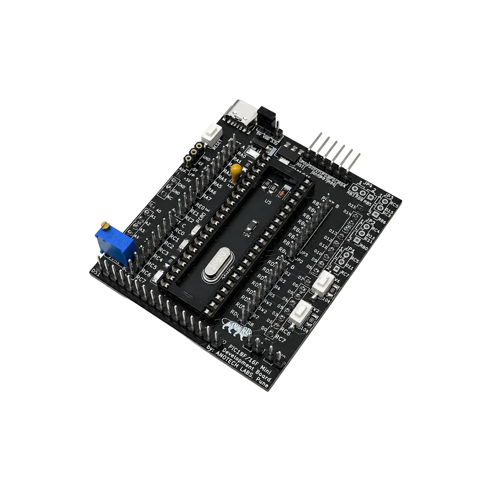
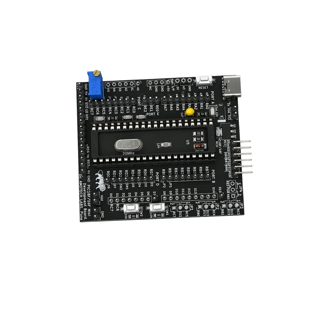
Amotech Labs PIC18F/16F Mini Development Board

₹590.00 (Inclusive of all taxes)
Out of Stock

The Amotech Labs PIC18F/16F Mini Development Board is a compact prototyping platform for 40-pin DIP PIC microcontrollers, powered via USB-C and featuring a PICkit 3/3.5 programming interface for streamlined firmware development and debugging.

Features

  • Supports a wide range of 40-pin DIP PIC16F and PIC18F microcontrollers for flexible project design.
  • Integrated PICkit 3/3.5 programming connector enables easy code upload and in-circuit debugging.
  • USB-C power input provides a stable +5V supply, simplifying setup and eliminating external power adapters.
  • Onboard analog input, digital I/O (LED, pushbuttons), and accessible MCU ports accelerate prototyping.
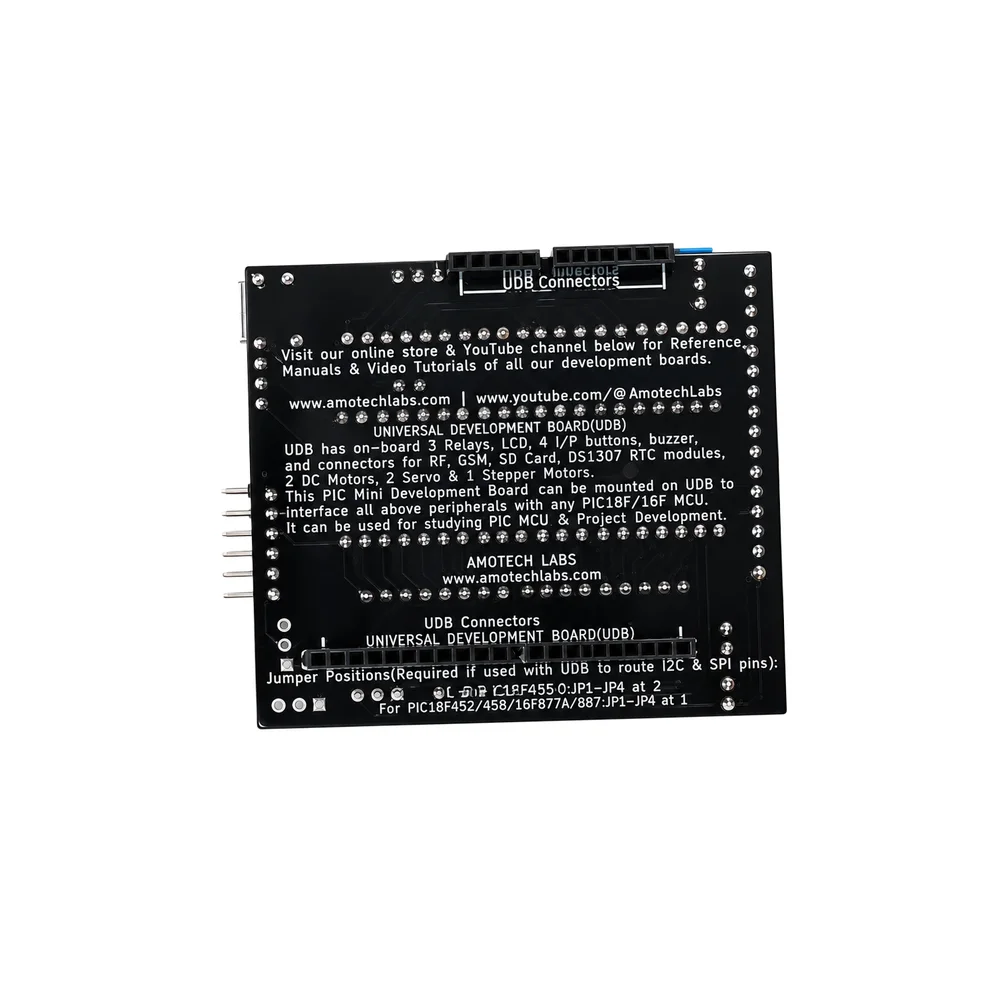
  • UDB expansion connector and configurable SPI/I²C jumpers allow seamless interfacing with sensors and modules.

Out of stock

Description

The Amotech Labs PIC18F/16F Mini Development Board is a dedicated platform for embedded developers and students working with Microchip Technology’s PIC microcontroller family. Its core design centers on a 40-pin DIP socket, providing broad compatibility with numerous PIC16F and PIC18F chips, which facilitates rapid MCU swapping and testing without soldering.

Power management is handled via a modern USB-C port, delivering a clean +5V rail to the board and connected peripherals. The integrated PICkit programming header streamlines the development workflow, allowing direct connection to common debuggers for flashing and real-time code execution control. Accessible port pins, an analog input channel, and basic digital I/O components like LEDs and tactile switches provide immediate feedback and input capabilities for initial circuit validation and functional testing.

Key Features

  • Universal 40-pin DIP socket compatible with PIC16F and PIC18F microcontroller families.
  • Direct PICkit 3/3.5 programming interface for seamless firmware upload and debugging.
  • Modern USB-C connector for reliable +5V power input and data connectivity.
  • Onboard reset switch and accessible MCU I/O ports (A, B, C, D, E) for rapid prototyping.
  • Dedicated analog input pin (A3) for interfacing sensors like LM35 temperature sensors or potentiometers.
  • Configurable SPI and I²C communication lines via jumper settings (JP1-JP4).
  • UDB expansion connector for adding custom shields or peripheral modules.
  • Compact form factor designed for bench-top development and educational use.

Applications

  • Educational platform for learning embedded systems and microcontroller programming.
  • Prototyping and testing environment for PIC-based sensor nodes and control systems.
  • Development base for hobbyist projects involving analog sensing, digital I/O, and serial communication.
  • Bench tool for engineers validating firmware on different PIC MCU variants before custom PCB design.

Technical Specifications

Item TypeMini Development Board
Supported MCUsPIC16F & PIC18F (40-pin DIP compatible)
Programming InterfacePICkit 3 / PICkit 3.5 connector
Input Voltage+5V via USB-C
Power ConnectorUSB-C
Digital OutputLED connected to RC2 (PWM capable)
Digital Inputs2 Push Buttons (RD2, RD3)
Analog InputA3 channel
Expansion InterfaceUDB Connector support
Communication RoutingSPI & I²C via Jumpers (JP1–JP4)
Dimensions70 x 58 x 20 mm
Weight26 g

Frequently Asked Questions

How do I program the microcontroller on this development board?

Connect a PICkit 3 or PICkit 3.5 programmer to the dedicated 6-pin header on the board. Use Microchip Technology's MPLAB X IDE or MPLAB IPE software to compile your code and flash the connected PIC microcontroller. Ensure the board is powered via the USB-C port or an external +5V supply during the programming process for stable operation.

What is the purpose of the jumpers labeled JP1 to JP4?

The JP1 to JP4 jumpers configure the serial communication lines for SPI and I²C protocols. By placing or removing these jumpers, you can route the SDA, SCL, MOSI, MISO, and SCK signals from the microcontroller to the expansion UDB connector. This allows you to easily interface with external SPI or I²C modules, sensors, or displays without manual wiring.

Can I use this board with 3.3V sensors despite its 5V logic?

The board operates at 5V logic levels from the USB-C supply. To interface with 3.3V sensors, you will need a logic level converter or voltage divider circuit on the I/O lines. The analog input pin (A3) is also referenced to 5V; ensure any connected analog sensor outputs a signal within the 0-5V range to avoid damaging the PIC's ADC.

Package Includes

  • 1 x Amotech Labs PIC18F/16F Mini Development Board (Only Board)

Additional Information

Weight 0.045 kg
Dimensions 12 × 8 × 3 cm