SKU: IOWC-0904
📋 GST Invoice Available

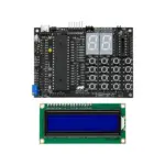
Amotech Labs PIC18F/16F Development Board w/ PIC18F452 & LCD

₹1,623.00 (Inclusive of all taxes)
Out of Stock

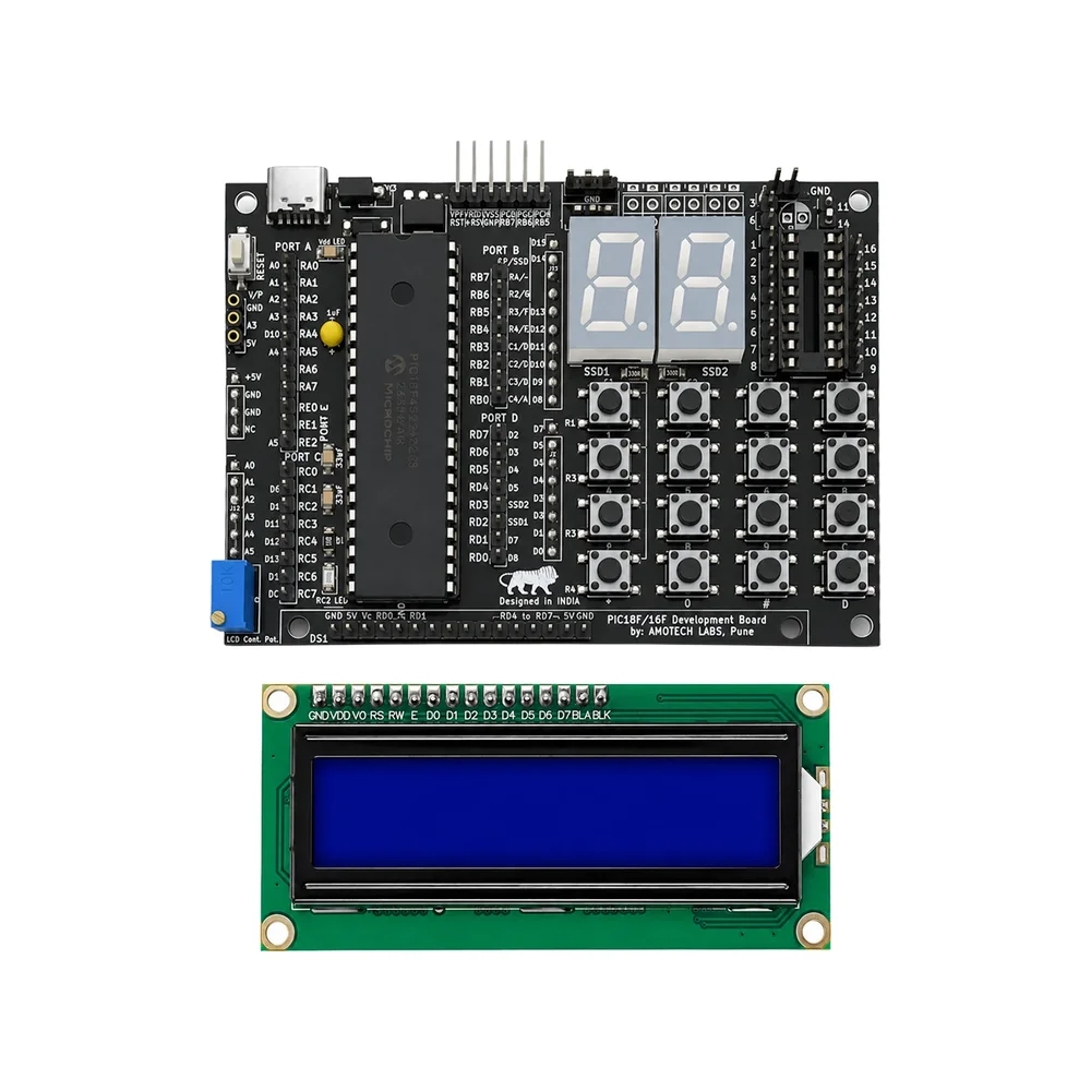
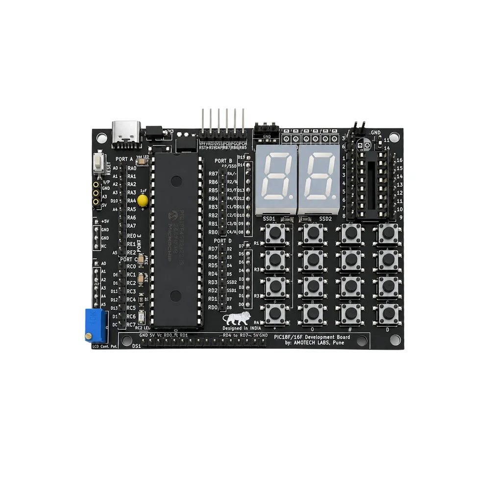
The Amotech Labs PIC18F/16F Development Board is a dedicated prototyping platform for 40-pin PIC microcontrollers, featuring a USB-C power interface, onboard programming connector, and integrated LCD, keypad, and displays for embedded systems development.

Features

  • Supports 40-pin PIC16F and PIC18F microcontrollers, including the pre-installed PIC18F452 IC for immediate development.
  • Integrated 4×4 keypad, dual seven-segment displays, and an LCD provide rich user I/O for interactive projects and debugging.
  • Features a PICkit 3/3.5 compatible programming connector and USB-C +5V power input for streamlined firmware flashing and operation.
  • Selectable 5V/3.3V operating voltage via jumper and extensive expansion connectors (UDB, breadboard-style) enable flexible peripheral integration.
  • Includes dedicated PWM-testing LED on RC2 and analog input channel for sensor interfacing, ideal for educational and prototyping workflows.

Out of stock

Description

The Amotech Labs PIC18F/16F Development Board is a comprehensive, all-in-one platform designed for embedded engineers and students working with Microchip Technology’s PIC microcontroller family. It provides a robust foundation for developing, testing, and deploying applications by integrating core MCU support with essential human-machine interface (HMI) components and a versatile expansion ecosystem.

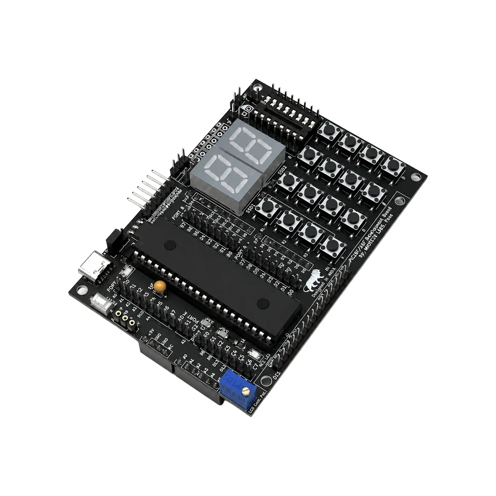
Built around a 40-pin DIP socket, the board natively accommodates a wide range of PIC16F and PIC18F devices, shipped with a PIC18F452 installed for out-of-the-box functionality. Its architecture emphasizes hands-on experimentation, featuring direct access to MCU ports, a dedicated programming header for PICkit tools, and a selectable 5V/3.3V power rail to match peripheral requirements. The inclusion of interactive elements like a Matrix keypad, dual seven-segment displays, and push buttons accelerates the development of user-controlled systems, while the PWM-capable LED and analog input channel facilitate signal testing and sensor integration.

Key Features

  • Dedicated 40-pin DIP socket supporting PIC16F and PIC18F microcontroller families for flexible project scaling.
  • Integrated human-machine interface with 4x4 keypad, dual seven-segment displays, and push buttons for interactive application development.
  • Onboard PICkit 3/3.5 compatible programming connector for direct firmware uploads without external adapters.
  • Dual-power rail system with jumper-selectable 5V or 3.3V operation to interface with a wide range of sensors and peripherals.
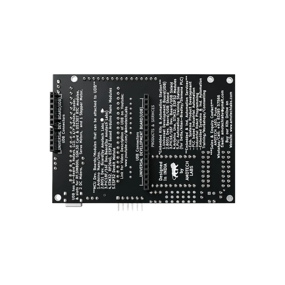
  • Comprehensive expansion via UDB connectors and breadboard-compatible headers for attaching shields, sensors, and custom circuits.
  • Includes dedicated PWM-testing LED on RC2 and an analog input channel (A3) for direct sensor signal measurement and prototyping.
  • USB-C +5V power input provides modern, reversible connectivity and stable power delivery for standalone operation.

Applications

  • Educational platform for learning embedded systems, microcontroller architecture, and C programming for PIC devices.
  • Rapid prototyping board for industrial control systems, sensor nodes, and basic human-machine interface (HMI) units.
  • Development testbed for hobbyist projects involving user input (keypads), numeric output (displays), and PWM control (LEDs, motors).
  • Foundation for custom embedded designs requiring easy access to PIC MCU pins, analog inputs, and expansion capabilities.

Technical Specifications

Microcontroller SupportPIC16F/18F (40-pin DIP compatible), includes PIC18F452 IC
Programming InterfacePICkit 3/3.5 Compatible Connector
Power InputUSB-C +5V
Operating Voltage5V / 3.3V (Selectable via jumper)
Input Interfaces4×4 Keypad, 2 Push Buttons (RD2, RD3)
Output Interfaces2x Seven Segment Display, PWM LED (RC2), LCD
Expansion InterfacesUDB Connector, Breadboard-style Headers
Analog InputA3 Channel (supports LM35 / Potentiometer)
Dimensions100 x 70 x 20 mm
Weight50 g

Frequently Asked Questions

How do I program the microcontroller on this Amotech Labs board?

Use a PICkit 3 or 3.5 programmer connected to the onboard 6-pin ICSP header. Install MPLAB X IDE or MPLAB IPE on your computer, connect the USB cable, select the correct PIC device (e.g., PIC18F452) in the software, compile your code, and click 'Program' to flash the firmware onto the MCU through the dedicated programming interface.

Can I use 3.3V sensors and peripherals with this development board?

Yes. Set the voltage selection jumper to the 3.3V position to power the board's I/O rails at 3.3V. Ensure any connected sensors or modules are compatible with this logic level. The MCU itself still operates at 5V from the USB input, but the jumper switches the voltage supplied to the expansion headers and some onboard components for safe peripheral interfacing.

What is the purpose of the A3 analog input channel?

The A3 channel is a dedicated analog input pin broken out to a header. It allows you to directly connect analog sensors like temperature sensors (LM35) or potentiometers to the PIC's ADC. You can read voltage values (0-5V) in your code to measure physical phenomena, making it ideal for data acquisition and sensor prototyping projects without additional circuitry.

Package Includes

  • 1 x Amotech Labs PIC18F/16F Development Board (with PIC18F452 IC and LCD)

Additional Information

Weight 0.111 kg
Dimensions 14 × 10 × 3 cm