
SKU: SENS-0203
📋 GST Invoice Available

AD8232 ECG Heart Sensor Module for Arduino w/ Electrode Pads & Cable

₹679.00 (Inclusive of all taxes)
Out of Stock

The AD8232 ECG Sensor Module is a dedicated signal conditioning front-end for extracting, amplifying, and filtering biopotential signals, providing a clean analog output compatible with Arduino and other 3.3V/5V microcontroller ADCs for heart rate monitoring and ECG waveform acquisition.

Features

  • Integrated AD8232 IC for ECG signal amplification and filtering in noisy conditions.
  • Provides analog output for direct connection to microcontroller ADC pins.
  • Features Leads-Off Detection (LO+, LO-) to indicate poor electrode contact.
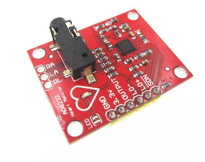
  • Includes 3.5mm jack for standard biomedical pads and breakout pins (RA, LA, RL) for custom electrode connections.
  • Compact module with shutdown pin for low-power operation and LED heartbeat indicator.

Out of stock

Description

The AD8232 module serves as a complete analog front-end for biopotential measurement, specifically optimized for electrocardiogram (ECG) signals. It employs the AD8232 integrated circuit, which acts as an instrumentation amplifier with built-in filtering to extract the small electrical activity of the heart (typically in the mV range) while suppressing motion artifacts, electrode half-cell potentials, and other common-mode noise. This conditioning enables reliable signal acquisition even with remote or dry electrodes.

The module outputs a single-ended analog voltage proportional to the processed ECG waveform, suitable for sampling by any microcontroller with an ADC, such as Arduino, ESP32, or Raspberry Pi Pico. Key operational features include a shutdown pin for power management, a dedicated LED that pulses with the QRS complex, and leads-off detection pins that go high when an electrode becomes disconnected, ensuring data integrity. It is designed for prototyping, fitness monitoring, and biomedical data acquisition projects.

Key Features

  • High-performance AD8232 signal conditioning IC for ECG and EMG applications.
  • Robust high-pass and low-pass filtering for clear signal extraction from noisy environments.
  • Leads-off detection circuit alerts the system to poor electrode-skin contact.
  • Convenient 3.5mm audio jack and direct breakout pins (RA, LA, RL) for flexible electrode attachment.
  • Low-power shutdown mode controlled via a dedicated digital pin.
  • Visual heartbeat feedback via an onboard pulsating LED indicator.
  • Simple 3.3V power supply and analog output interface for easy microcontroller integration.
  • Compact, high-value build optimized for educational and prototyping use.

Applications

  • Prototype heart rate monitors for fitness and exercise tracking devices.
  • Educational projects for biomedical engineering and physiology demonstrating ECG signal acquisition.
  • Remote patient monitoring systems for capturing basic cardiac rhythm data.
  • Biometric input for interactive art installations or human-computer interface projects.
  • Research and data logging of heart rate variability (HRV) in controlled environments.

Technical Specifications

KeyValue
Core ICAD8232
Primary FunctionECG/Biopotential Signal Conditioning
Output SignalAnalog Voltage
Supply Voltage3.3V
Operating Temperature-40°C to +85°C
InterfaceAnalog Output, Digital Shutdown (SDN), Leads-Off Detection (LO+, LO-)
Electrode Connection3.5mm Jack & RA/LA/RL Breakout Pins
Module Dimensions (LxW)36mm x 30mm
Module Weight5g
Included Cable Length50cm

Frequently Asked Questions

What is the operating voltage for the AD8232 module, and can I power it with 5V?

The module is designed for a 3.3V supply. Applying 5V directly to the VCC pin may damage the sensitive AD8232 IC. If your system only has 5V logic, use a voltage regulator or level shifter to provide a clean 3.3V supply to the module's 3.3V pin.

How do I connect electrodes to this module?

You have two options. For quick setup, use the included cable with snap connectors to attach standard disposable electrodes and plug the other end into the module's 3.5mm jack. For custom wiring, use the breakout pins: connect your Right Arm (RA), Left Arm (LA), and Right Leg (RL) electrodes to the corresponding labeled pins on the board. The RL pin is typically used as a reference/drive.

What do the LO+ and LO- (Leads-Off) pins indicate, and how do I use them?

The LO+ and LO- pins are digital outputs from the AD8232 IC. They go to a logic HIGH state when the corresponding electrode (for LO+) or the reference electrode (for LO-) loses proper contact with the skin. You can connect these pins to digital inputs on your microcontroller to detect and alert users of poor signal quality or detached electrodes.

Can I use this module to get a digital heart rate reading directly?

No, the module provides an analog output representing the raw ECG waveform voltage. To obtain a heart rate in beats per minute (BPM), you must sample this analog signal with a microcontroller's ADC and implement an algorithm (e.g., detecting QRS peaks) to calculate the period between heartbeats. Numerous open-source libraries exist for this purpose on platforms like Arduino.

Is the AD8232 module suitable for medical diagnosis?

No. This is a prototyping and educational tool intended for non-critical fitness, wellness, and engineering projects. It is not a certified medical device, is not calibrated for clinical use, and must not be used to diagnose, treat, or monitor any medical condition.

Package Includes

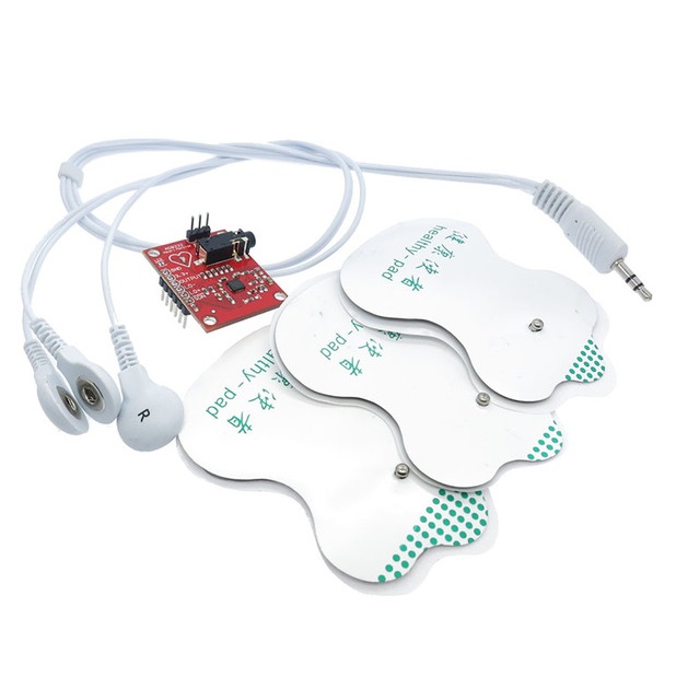
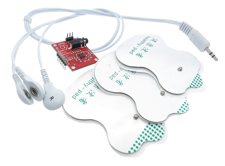
  • 1 x AD8232 ECG Sensor Module
  • 1 x Sensor Cable (50cm)
  • 3 x Disposable Electrode Pads

Additional Information

Weight 0.005 kg
Dimensions 3.6 × 3 cm