SKU: SENS-2796
📋 GST Invoice Available

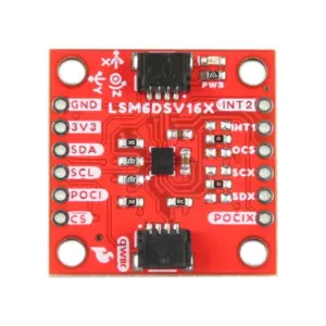
Adafruit LIS3DH Triple-Axis Accelerometer ±2/4/8/16g - I2C/SPI, STEMMA QT/Qwiic

₹799.00 (Inclusive of all taxes)
Out of Stock

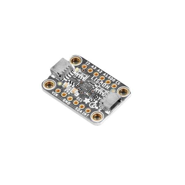
The Adafruit LIS3DH is a versatile, low-power triple-axis accelerometer breakout board offering configurable sensitivity ranges from ±2g to ±16g. It features I2C and SPI communication, is compatible with 3.3V and 5V logic systems, and includes convenient STEMMA QT/Qwiic connectors for plug-and-play prototyping.

Features

  • Triple-axis MEMS accelerometer with ±2g, ±4g, ±8g, or ±16g user-selectable full-scale ranges.
  • Ultra-low power operation down to 2 µA, with programmable data rates from 1 Hz to 5 kHz.
  • I2C (two selectable addresses) and SPI digital interfaces with 3.3V/5V logic compatibility.
  • Integrated features for tap, double-tap, orientation, and free-fall detection.
  • Includes three auxiliary 10-bit ADC inputs accessible via the I2C bus.

Out of stock

Description

The Adafruit LIS3DH breakout board provides easy access to the STMicroelectronics LIS3DH MEMS accelerometer, a widely used chip known for its performance and configurability. The sensor delivers three-axis acceleration data with 10-bit precision, making it suitable for a broad spectrum of motion-sensing applications from basic tilt detection to complex vibration analysis.

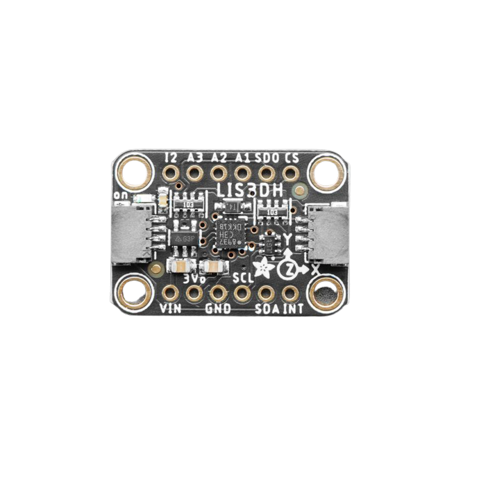
Engineered for flexibility, the module supports both I2C and SPI serial communication protocols, allowing seamless integration with popular microcontrollers like Arduino, Raspberry Pi, and ESP32. The updated version features STEMMA QT and Qwiic compatible connectors, enabling solderless connection to compatible development ecosystems. The board includes 2.5mm mounting holes for secure installation in projects.

Key Features

  • Configurable High-Performance Sensing: Selectable full-scale ranges (±2g, ±4g, ±8g, ±16g) and data output rates (1 Hz to 5 kHz) for optimized application-specific performance.
  • Advanced Motion Detection: Built-in algorithms for reliable detection of single/double-tap events, 6D orientation changes, and free-fall conditions.
  • Dual-Protocol Interface: Offers both I2C (with two address options to avoid bus conflicts) and high-speed SPI for communication flexibility.
  • Extended Analog Inputs: Three additional 10-bit ADC channels allow the module to read other analog sensors directly, consolidating data acquisition.
  • Plug-and-Play Connectivity: STEMMA QT / Qwiic 4-pin JST-SH connectors enable rapid prototyping without soldering, alongside standard 0.1" pitch headers.
  • Optimized Power Management: Features ultra-low current consumption modes, making it ideal for battery-powered and portable devices.

Applications

  • Wearable device motion tracking and gesture recognition.
  • Robotics platform stabilization, tilt sensing, and impact detection.
  • Industrial equipment vibration monitoring and predictive maintenance.
  • IoT sensor nodes for orientation-based triggering and low-power logging.
  • Prototyping interactive installations and game controllers.

Technical Specifications

Manufacturer / BrandAdafruit
Core ComponentSTMicroelectronics LIS3DH
Sensor TypeTriple-Axis Digital Accelerometer
Full-Scale Range±2g, ±4g, ±8g, ±16g (User Selectable)
Output Resolution10-bit
Output Data Rate1 Hz to 5 kHz (Programmable)
Communication InterfaceI2C (2 addresses), SPI
Logic Voltage Compatibility3.3V, 5V
Supply Voltage (VDC)3.3V to 5V
Current Consumption (Low Power)Down to 2 µA
Additional FeaturesTap/Double-Tap, Orientation, Free-Fall Detection; 3x Auxiliary 10-bit ADC Inputs
Connector TypeSTEMMA QT / Qwiic JST-SH, 0.1" Pitch Headers
Mounting2 x 2.5mm Mounting Holes
Board Dimensions (L x W x H)20.6 x 20.3 x 2.6 mm

Frequently Asked Questions

What is the operating voltage range for the Adafruit LIS3DH breakout board?

The board is designed to operate from a 3.3V to 5V DC supply. Its I2C and SPI logic levels are compatible with both 3.3V and 5V microcontroller systems, making it suitable for use with Arduino Uno (5V), Raspberry Pi (3.3V), ESP32, and similar platforms without requiring a logic level shifter.

How do I select between the I2C and SPI communication interfaces?

The interface is selected via solder jumpers on the back of the breakout board. By default, it is configured for I2C communication. To use SPI, you must cut the relevant trace for the CS (Chip Select) pin and solder the Jumper to enable it. The board's pinout and labeling clearly indicate the configuration points for each protocol.

Can I use the auxiliary ADC inputs on the LIS3DH simultaneously with the accelerometer data?

Yes, the three auxiliary 10-bit ADC inputs are multiplexed and can be read over the same I2C bus used for the accelerometer. This allows you to read external analog sensors (like a potentiometer or light sensor) without requiring additional ADC channels on your main microcontroller, though sampling is sequential and managed through the LIS3DH's internal registers.

What are the key differences between the older and newer versions of this Adafruit breakout?

The newer version, shipped from December 2020 onwards, adds STEMMA QT and Qwiic compatible 4-pin JST-SH connectors for solderless plug-and-play connectivity with compatible boards. The core LIS3DH sensor and functionality (I2C/SPI, ranges, detection features) remain identical. Both versions include standard 0.1" headers.

Package Includes

  • 1 x Adafruit LIS3DH Triple-Axis Accelerometer Breakout Board
  • 1 x Breakaway Header Strip

Additional Information

Weight 0.006 kg
Dimensions 2.06 × 2.03 × 0.26 cm