SKU: IOWC-1084
📋 GST Invoice Available

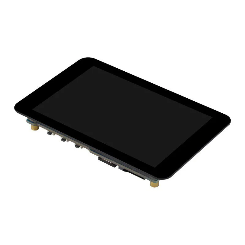
Waveshare ESP32-S3 3.5-Inch Capacitive Touch Display Development Board

₹3,409.00 (Inclusive of all taxes)
Out of Stock

The Waveshare ESP32-S3 3.5-Inch Capacitive Touch Display Development Board integrates a dual-core ESP32-S3R8 MCU with Wi-Fi/Bluetooth 5.0, a high-resolution IPS touchscreen, and extensive peripherals including an IMU, RTC, and camera interface, ideal for Arduino IDE, ESP-IDF, and MicroPython-based AIoT applications.

Features

  • Features a 3.5-inch capacitive touch IPS display with 320×480 resolution and 262K colors, driven by ST7796S via SPI for crisp visuals and FT6336 via I2C for responsive touch input.
  • Powered by the ESP32-S3R8 dual-core Xtensa LX7 processor (up to 240MHz) with 8MB PSRAM and 16MB Flash, supporting robust 2.4GHz Wi-Fi (802.11 b/g/n) and Bluetooth 5 LE connectivity.
  • Integrated QMI8658 6-axis IMU (accelerometer & gyroscope) and PCF85063 RTC chip with backup battery header enable advanced motion sensing and timekeeping for portable IoT devices.
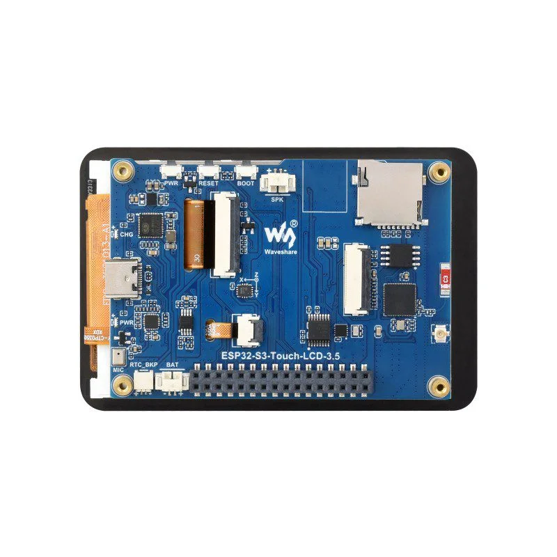
  • Comprehensive I/O includes a camera interface (compatible with OV2640/OV5640), TF card slot, USB Type-C, multiple GPIOs, UART, I2C, and programmable BOOT/PWR buttons for flexible peripheral expansion.
  • Efficient AXP2101 power management IC supports 3.7V Li-ion battery charging/discharging, multiple voltage outputs, and optimized power profiles for extended battery life in field deployments.

Out of stock

Description

The Waveshare ESP32-S3 3.5-Inch Capacitive Touch Display Development Board is a feature-rich AIoT platform designed for developers building interactive, connected devices. It combines the processing power of Espressif’s ESP32-S3R8 dual-core microcontroller with a high-quality 3.5-inch IPS capacitive touchscreen, creating an all-in-one solution for GUI-based IoT applications, portable instruments, and smart control panels.

Architecturally, the board leverages the ESP32-S3’s integrated 2.4GHz Wi-Fi and Bluetooth 5.0 radio subsystem with an onboard PCB antenna for reliable wireless communication. The inclusion of 8MB PSRAM and 16MB Flash memory supports complex graphics buffers and substantial application code. The integrated QMI8658 6-axis inertial measurement unit (IMU) and PCF85063 real-time clock (RTC) with battery backup facilitate motion-aware and time-synchronized operations, critical for wearable tech and data loggers.

Key Features

  • High-resolution 3.5-inch IPS capacitive touch display with 320x480 pixels and 262K color depth for vibrant graphical user interfaces.
  • ESP32-S3R8 dual-core processor running at up to 240MHz, coupled with 8MB PSRAM and 16MB Flash for demanding computational and graphical tasks.
  • Integrated wireless connectivity via 2.4GHz Wi-Fi (802.11 b/g/n) and Bluetooth 5 Low Energy (LE) with an onboard antenna.
  • Comprehensive sensor suite including a 6-axis IMU (accelerometer & gyroscope) and a precise RTC with dedicated backup battery circuit.
  • Dedicated camera interface compatible with popular OV2640 and OV5640 modules, enabling computer vision and image capture applications.
  • Advanced AXP2101 power management IC supporting Li-ion battery operation, charging, and multiple regulated voltage outputs for system efficiency.
  • Expansion interfaces include a microSD (TF) card slot, USB Type-C for programming/power, and a rich set of GPIOs broken out for peripherals.
  • Programmable BOOT and PWR buttons alongside a speaker output facilitate custom user interface and audio feedback development.

Applications

  • Smart home control panels and interactive dashboards with local GUI and cloud connectivity.
  • Portable data loggers and field measurement instruments with sensor readouts and touch-based navigation.
  • Wearable tech and fitness devices leveraging the IMU for motion tracking and the display for real-time feedback.
  • Prototyping AIoT devices with camera integration for basic computer vision, object detection, or barcode scanning.
  • Industrial HMIs (Human-Machine Interfaces) for monitoring and controlling equipment via Wi-Fi or Bluetooth.

Technical Specifications

Microcontroller / SoCESP32-S3R8 (Xtensa 32-bit LX7 Dual-Core, up to 240MHz)
Wireless Protocols2.4GHz Wi-Fi (802.11 b/g/n), Bluetooth 5.0 LE
Display3.5-inch IPS Capacitive Touch, 320 x 480 pixels, 262K Colors
Display Driver / Touch ControllerST7796S (SPI), FT6336 (I2C)
Memory512KB SRAM, 384KB ROM, 8MB PSRAM, 16MB External Flash
Onboard SensorsQMI8658 6-axis IMU (3-axis Accel + 3-axis Gyro), PCF85063 RTC
Power ManagementAXP2101 IC (Li-ion Charging, Multi-Output)
InterfacesUSB Type-C, Camera Interface (OV2640/OV5640), TF Card Slot, I2C, UART, SPI, Multiple GPIOs
AntennaOnboard PCB Antenna
Dimensions (L x W)91mm x 60mm (approx. 9.1cm x 6.0cm)

Frequently Asked Questions

What development frameworks are supported for programming this Waveshare ESP32-S3 display board?

The board is fully compatible with the Arduino IDE using the ESP32 board package, Espressif's official ESP-IDF framework for advanced features, and MicroPython for rapid scripting. You must install the correct board definitions and drivers. The USB Type-C port is used for uploading code and serial debugging. Ensure you select the correct target (e.g., ESP32-S3) and configure the display and touch drivers in your project settings for full functionality.

How do I connect and use an external camera with the onboard camera interface?

The board features a standard camera interface compatible with modules like the OV2640 and OV5640. You connect the camera's flex cable to the board's FPC connector, ensuring proper alignment. In your code (using ESP-IDF or Arduino with the ESP32 camera library), you must initialize the camera by defining the pin mapping, sensor model, and resolution. The interface uses a parallel DVP (Digital Video Port) protocol. Power for the camera is supplied directly from the board's 3.3V rail through the connector.

What is the power supply requirement and how does the battery management work?

The board can be powered via the USB Type-C port (5V) or through the dedicated 3.7V Li-ion battery header. The integrated AXP2101 PMIC manages power distribution, battery charging, and provides multiple stable voltage rails (e.g., 3.3V, 2.5V) to the system components. To use battery power, connect a single-cell 3.7V Li-ion or Li-Po battery to the MX1.25 header. The RTC can be backed up by a separate small battery (like a CR1220) connected to its dedicated header, ensuring timekeeping during main battery swaps.

Can I use the microSD (TF) card slot for data logging and how is it accessed in code?

Yes, the TF card slot supports standard microSD cards (formatted with FAT filesystem) for data logging, media storage, or configuration files. It is connected to the ESP32-S3 via the SDMMC or SPI host controller, depending on the library. In Arduino, you can use the 'SD_MMC' or 'SD' libraries. In ESP-IDF, use the 'sdmmc' or 'sdspi' driver components. You must initialize the card, mount the filesystem, and then perform read/write operations. Ensure the card is inserted before power-up for reliable detection.

How do I calibrate the capacitive touch screen and adjust the display brightness?

The FT6336 touch controller typically works out-of-the-box, but for precise calibration, you may need to run a calibration routine provided in example code from Waveshare or the ESP-IDF touch calibration component. Display brightness is controlled via the backlight pin using PWM (Pulse Width Modulation). You can define the backlight GPIO pin in your code and use the 'ledc' peripheral in ESP-IDF or the 'analogWrite' function in Arduino (on supported pins) to dim or brighten the screen, helping to manage overall power consumption.

Package Includes

  • 1 x ESP32-S3-Touch-LCD-3.5 Development Board
  • 1 x 6Ω 1W Speaker

Additional Information

Weight 0.079 kg
Dimensions 9.1 × 6 cm