SKU: SENS-3298
📋 GST Invoice Available

TCS3200 Color Recognition Sensor Module for Arduino - 3-5V RGB Detection

₹599.00 (Inclusive of all taxes)
Out of Stock

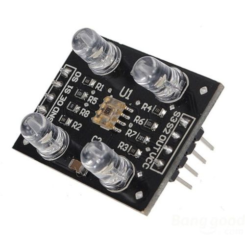
The TCS3200 Color Recognition Sensor Module is a programmable RGB color sensor compatible with 3.3V and 5V logic systems like Arduino, Raspberry Pi, and ESP32. It outputs a square wave frequency proportional to detected light intensity for precise color identification.

Features

  • Programmable RGB color sensor with TCS3200 IC for accurate color detection.
  • Wide 3V to 5V operating voltage range for compatibility with 3.3V and 5V MCU platforms.
  • Onboard white LEDs provide consistent illumination independent of ambient light.
  • Direct digital frequency output communicates easily with microcontrollers via standard 0.1″ headers.
  • Selectable photodiode filter (Red, Green, Blue, Clear) via S2/S3 control pins for spectral analysis.

Out of stock

Description

The TCS3200 Color Recognition Sensor Module utilizes a high-quality light-to-frequency converter IC. It senses color through an array of photodiodes with integrated Red, Green, and Blue filters, outputting a square wave whose frequency is directly proportional to the intensity of the selected color. This digital output method provides high noise immunity and simplifies interface with microcontrollers.

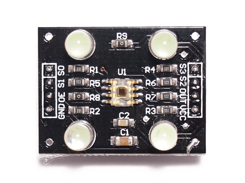
The module includes four white LEDs to illuminate the target, ensuring consistent readings across varying ambient light conditions. All control pins (S0, S1 for frequency scaling; S2, S3 for filter selection; OE for output enable) are broken out to standard 2.54mm pitch headers, making it ideal for prototyping on breadboards or integration into custom PCBs. The sensor operates across a wide voltage range, supporting both 3.3V and 5V logic systems commonly found in Arduino, Raspberry Pi, and ESP32 development environments.

Key Features

  • High-resolution light-to-frequency conversion for precise color intensity measurement.
  • Programmable color filter selection (Red, Green, Blue, Clear) via digital control pins S2 and S3.
  • Selectable output frequency scaling (100%, 20%, 2%) via S0 and S1 pins for optimized reading speed and resolution.
  • Integrated white LED illumination ensures stable operation in low or variable ambient light.
  • Low-profile surface-mount package with all signals broken out to standard 0.1" headers for easy prototyping.
  • Wide 2.7V to 5.5V supply range compatible with 3.3V and 5V microcontroller systems.
  • Digital output (OUT) provides a clean square wave, simplifying MCU interface via frequency measurement or pulse counting.

Applications

  • Color sorting and matching systems in light industrial automation or robotics.
  • RGB LED color calibration and feedback control for dynamic lighting systems.
  • Product quality inspection based on color consistency or presence.
  • Educational projects for teaching color theory, sensor interfacing, and signal processing with Arduino.
  • Interactive art installations or displays that respond to colored objects or markers.

Technical Specifications

Model / ICTCS3200 Color Sensor Module
Operating Voltage3V to 5V DC (2.7V - 5.5V IC range)
Output SignalDigital Square Wave (Frequency)
Detection PrincipleRGB Filtered Photodiode Array
Filter SelectionRed, Green, Blue, Clear (via S2/S3)
Frequency Scaling100%, 20%, 2% (via S0/S1)
Output EnableActive Low (OE pin)
Onboard Illumination4x White LEDs
Interface0.1" Pitch Headers
Module Dimensions (LxW)32 mm x 25 mm
Module Weight4 g

Frequently Asked Questions

What is the operating voltage range for the TCS3200 module?

The module is designed to operate from 3V to 5V DC, which covers the standard 3.3V and 5V logic levels used by platforms like Arduino, ESP32, and Raspberry Pi. The underlying TCS3200 IC itself can function from 2.7V to 5.5V, providing flexibility in various system designs.

How do I select which color (Red, Green, Blue) to measure?

Color selection is controlled digitally via the S2 and S3 pins. Setting S2=LOW, S3=LOW selects the red filter; S2=LOW, S3=HIGH selects blue; S2=HIGH, S3=LOW selects clear (no filter); and S2=HIGH, S3=HIGH selects green. Your microcontroller code must set these pins accordingly before taking a frequency reading from the OUT pin.

How do I read data from the TCS3200 sensor module?

The module outputs a square wave on the OUT pin. The frequency of this wave is proportional to the intensity of the currently selected color. You read the data by measuring this frequency using your microcontroller's input capture, timer, or pulse-counting functions. The S0 and S1 pins allow you to scale the output frequency (100%, 20%, 2%) to match your MCU's measurement capabilities.

What is the purpose of the OE (Output Enable) pin?

The OE pin is an active-low output enable. When held LOW, the frequency output on the OUT pin is active. When pulled HIGH, the output is disabled (high-impedance). This can be useful for power saving or for sharing a single microcontroller input pin among multiple sensors in a multiplexed setup.

Package Includes

  • 1 x TCS3200 Color Recognition Sensor Module

Additional Information

Weight 0.004 kg
Dimensions 3.2 × 2.5 cm