SKU: SBCD-0337
📋 GST Invoice Available

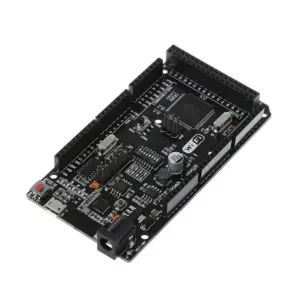
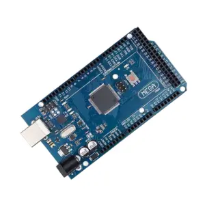
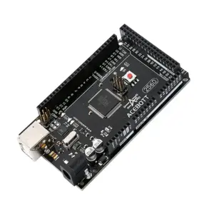
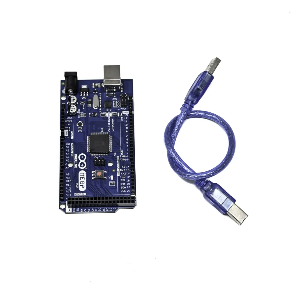
Mega R3 ADK Development Board with USB Cable

₹2,979.00 (Inclusive of all taxes)
Out of Stock

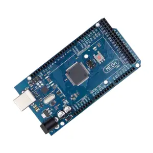
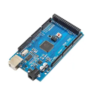
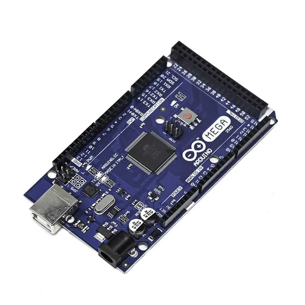
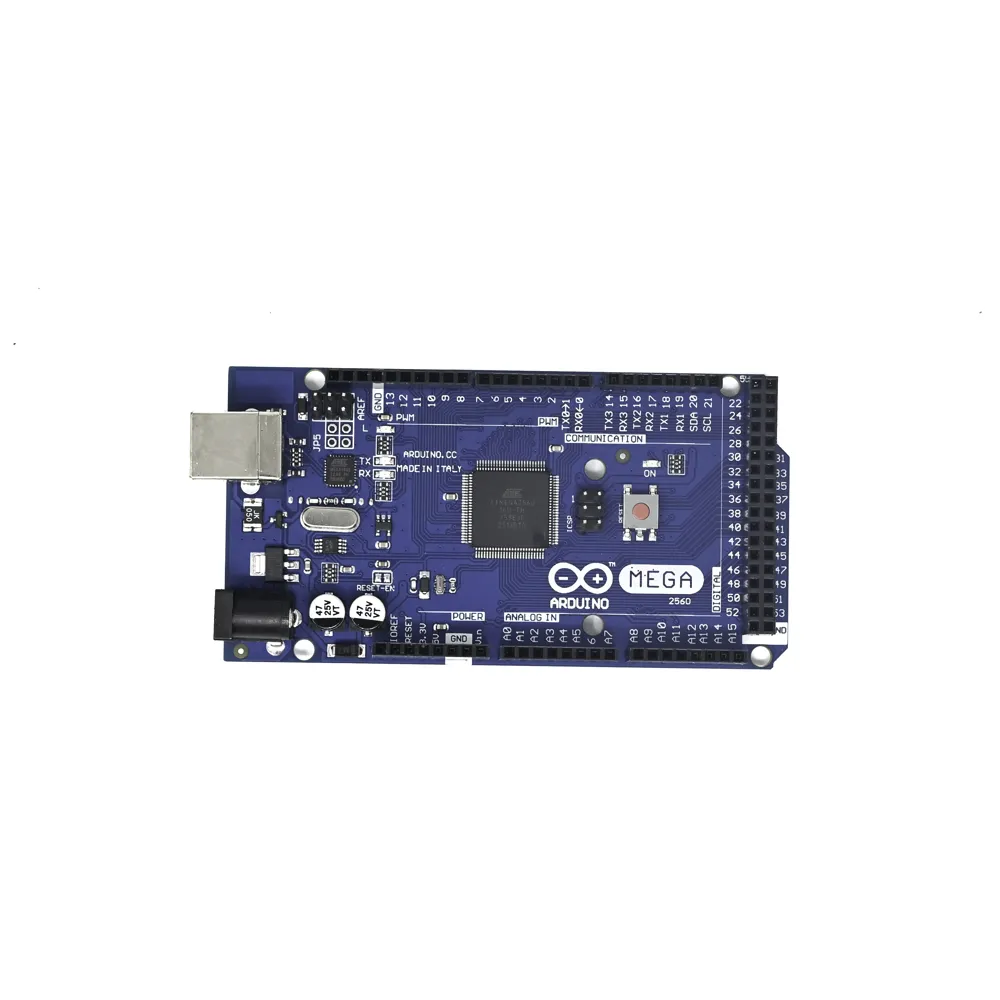
The Mega R3 Android Accessory Development Kit (ADK) is an ATmega2560-based microcontroller board featuring a USB host interface for seamless connectivity with Android devices via the integrated MAX3421e IC. Designed for Android accessory development, it provides extensive I/O capabilities for a wide range of projects.

Features

  • ATmega2560 microcontroller operating at 16 MHz.
  • Integrated MAX3421e USB Host for direct Android device connectivity.
  • Features 54 digital I/O pins (15 PWM) and 16 analog inputs.
  • 256KB Flash memory, 8KB SRAM, and 4KB EEPROM.
  • Includes a USB cable for immediate out-of-the-box use.

Out of stock

Description

The Mega R3 Android Accessory Development Kit (ADK) is a powerful microcontroller board built around the ATmega2560. Its distinguishing feature is an integrated USB host interface, facilitated by the MAX3421e IC, enabling direct communication with Android-based phones. This board offers a comprehensive set of I/O, including 54 digital input/output pins (15 capable of PWM output), 16 analog inputs, and four hardware UARTs for serial communication. The Revision 3 board incorporates a 1.0 pin-out with dedicated SDA, SCL, and IOREF pins, enhancing compatibility with future shields and a more robust reset circuit.

Powering the Mega R3 ADK is flexible, supporting either the USB connection or an external power supply, with automatic source selection. External power can be delivered via an AC-to-DC adapter (7-12V recommended, 6-20V limits) or battery. The board’s design, particularly its USB Host capability, allows it to provide power to connected Android phones, offering up to 500mA total when USB-powered. For applications requiring more power, the external regulator can supply up to 1500mA, with 750mA allocated for the phone and board, and an additional 750mA for connected actuators and sensors, provided the power supply can meet this demand.

Memory resources include 256 KB of flash memory for code storage (with 8 KB reserved for the bootloader), 8 KB of SRAM, and 4 KB of EEPROM. Beyond standard digital and analog I/O, the board supports various communication protocols like SPI (pins 50-53), TWI/I2C (pins 20 and 21), and multiple UARTs. It features a built-in LED on pin 13 and an AREF pin for analog reference voltage adjustments. A resettable polyfuse offers protection against overcurrent conditions on the USB port, safeguarding connected computers. The board’s physical characteristics ensure compatibility with most Arduino Uno/Duemilanove shields, although I2C pin locations differ.

Key Features

  • ATmega2560 Microcontroller for robust processing capabilities.
  • MAX3421e USB Host Controller enables direct communication with Android devices and other USB peripherals.
  • Extensive I/O: 54 digital pins (15 PWM capable) and 16 analog input pins.
  • Multiple hardware serial ports (4 UARTs) for versatile communication.
  • 1.0 pin-out with dedicated SDA, SCL, and IOREF pins for enhanced shield compatibility.
  • Integrated ATmega8U2 USB-to-serial converter for seamless PC connectivity.
  • Software-reset capability via DTR line for streamlined code uploads.
  • Resettable polyfuse protects computer USB ports from shorts and overcurrent.
  • Flexible power options: USB or external supply (6-20V limits, 7-12V recommended).

Applications

  • Android accessory development and prototyping
  • Controlling Canon cameras via USB
  • Interfacing with USB keyboards, mice, and game controllers (Wiimote, PS3)
  • Embedded systems requiring USB host capabilities
  • Educational robotics and IoT projects

Technical Specifications

MicrocontrollerATmega2560
Operating Voltage5V
Input Voltage (Recommended)7-12V
Input Voltage (Limits)6-20V
Digital I/O Pins54 (15 PWM)
Analog Input Pins16
DC Current per I/O Pin40 mA
DC Current for 3.3V Pin50 mA
Flash Memory256 KB (8 KB for bootloader)
SRAM8 KB
EEPROM4 KB
Clock Speed16 MHz
USB Host ControllerMAX3421E
Length10.152 cm
Width5.33 cm
Weight0.036 kg

Frequently Asked Questions

What is the primary function of the MAX3421e chip on the Mega R3 ADK?

The MAX3421e acts as a USB Host controller, enabling the Mega R3 ADK to connect and communicate directly with USB devices, particularly Android smartphones. This facilitates the development of USB-based accessories for Android platforms, expanding the board's interactive capabilities significantly.

What are the power requirements and recommendations for the Mega R3 ADK?

The board can be powered via USB (5V) or an external supply (6-20V limits, 7-12V recommended). For optimal stability, supplying less than 7V may affect the 5V output, and more than 12V risks overheating the voltage regulator. A power supply of 1.5A is needed for full current utilization.

How does the Mega R3 ADK handle firmware uploads and resets?

It comes with a pre-burned bootloader, allowing code uploads via the Arduino IDE over USB without an external programmer. Additionally, it supports software-driven resets via the DTR line, streamlining the upload process and enabling faster iteration during development through the virtual COM port.

What distinguishes the Mega R3 ADK from a standard Mega 2560?

The primary distinction is the integrated MAX3421e USB Host controller, which provides the ability to directly interface with USB devices, including Android phones. It also features a stronger reset circuit and revised 1.0 pin-out for improved shield compatibility and future-proofing.

Package Includes

  • 1 x Mega R3 Android Accessory Development Kit (ADK) board
  • 1 x USB cable

Additional Information

Weight 0.036 kg
Dimensions 10.152 × 5.33 cm