SKU: SENS-1188
📋 GST Invoice Available

MMA7361 3-Axis Low-g Accelerometer Module - 1.5g/6g Selectable Range, 5V/3.3V Compatible

₹659.00 (Inclusive of all taxes)
Out of Stock

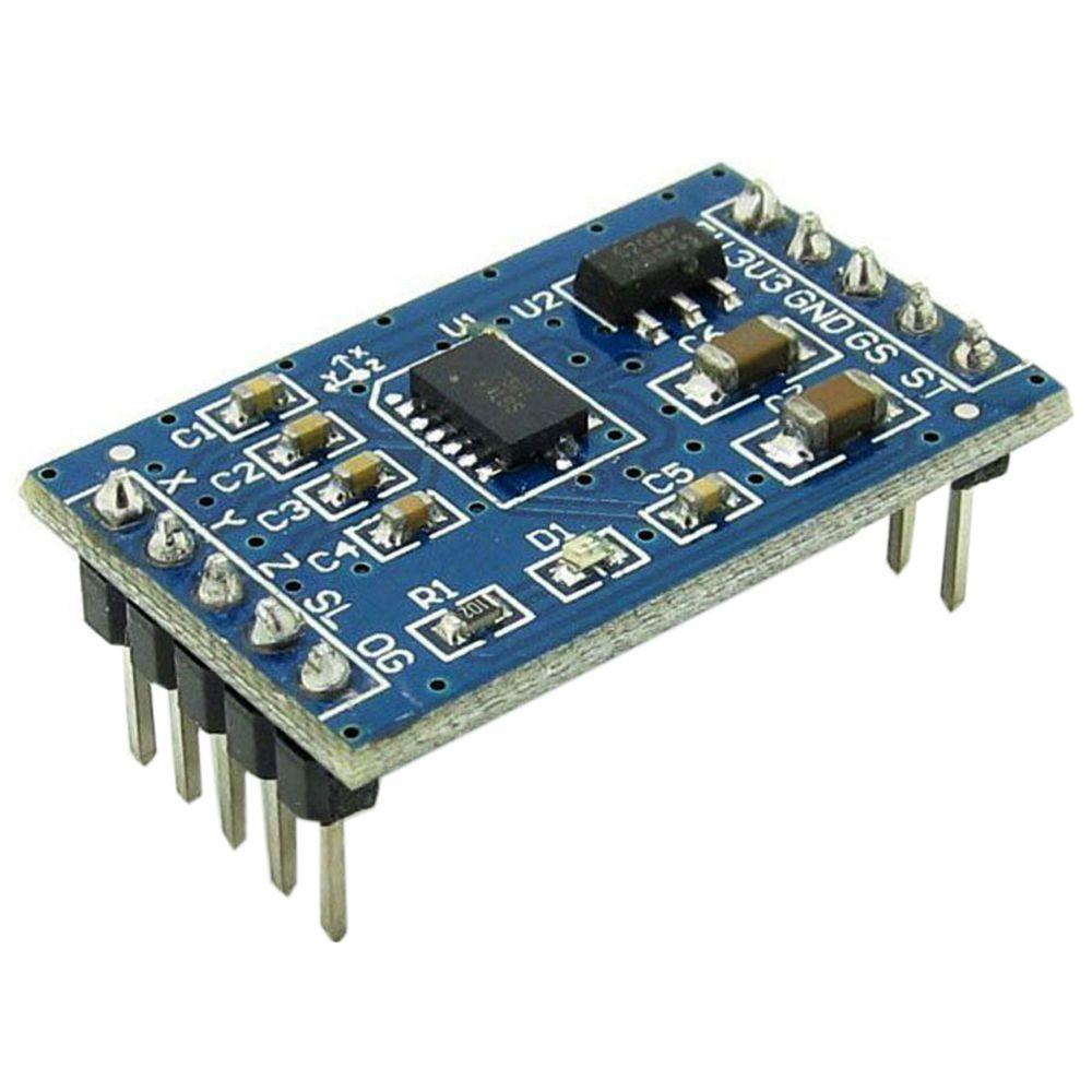
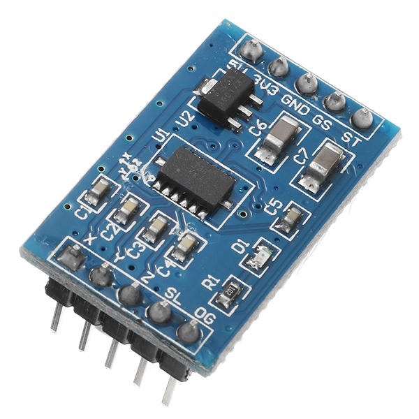
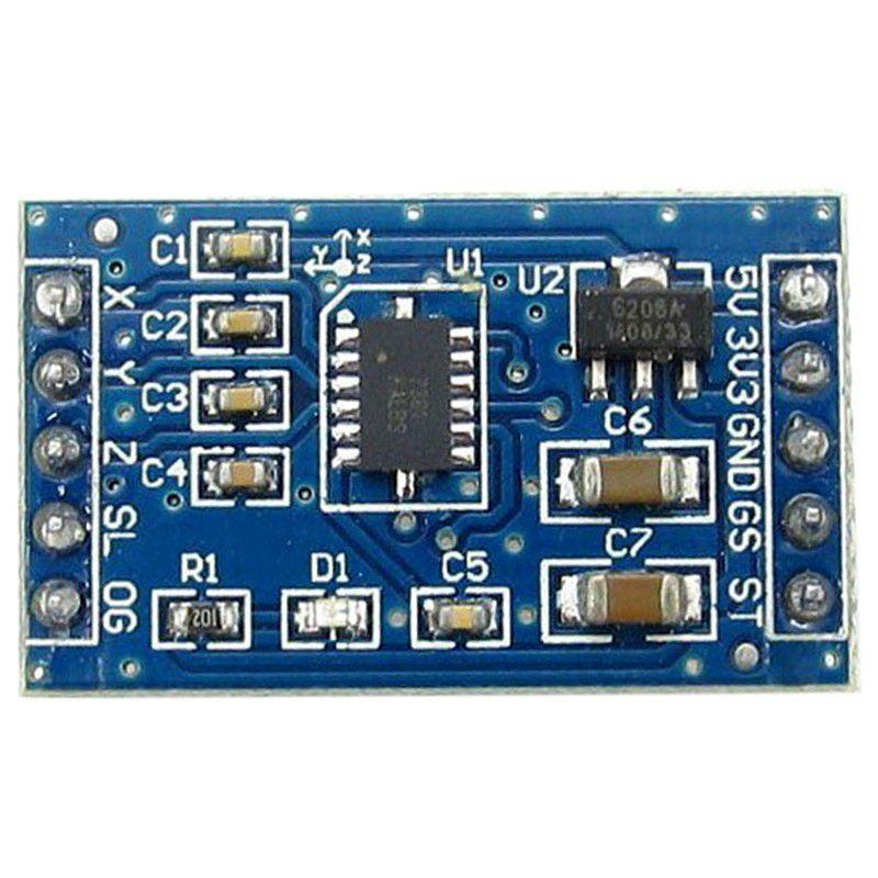
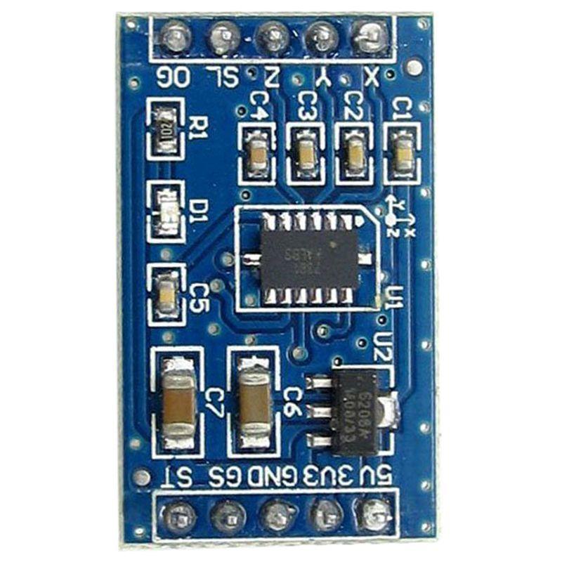
The MMA7361 3-axis capacitive accelerometer module provides low-g acceleration and tilt sensing with selectable ±1.5g or ±6g ranges, compatible with 5V and 3.3V microcontroller systems like Arduino, Raspberry Pi, and ESP32. It features low power consumption and analog outputs for each axis.

Features

  • Tri-axis capacitive MEMS accelerometer with ±1.5g / ±6g selectable ranges.
  • Low power operation: 400 µA active current, 3 µA sleep mode.
  • Wide supply voltage compatibility: 3.3V to 5V DC via onboard RT9161 LDO regulator.
  • Fast enable response time of 0.5 ms for power-sensitive applications.
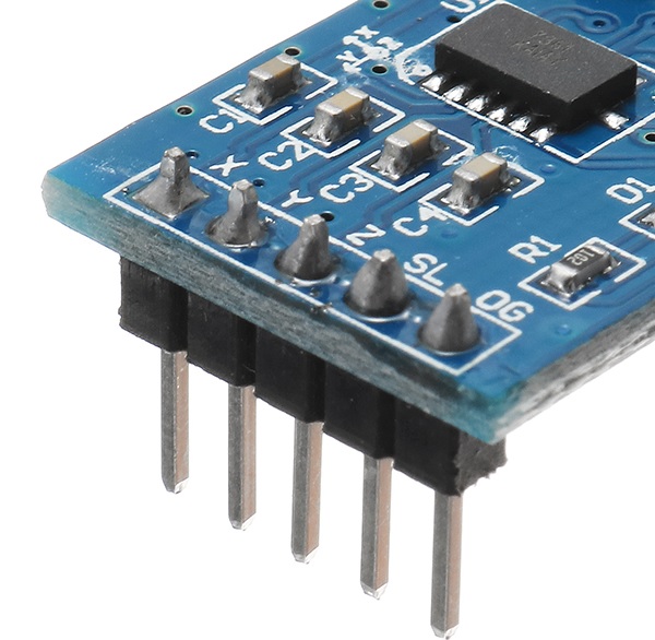
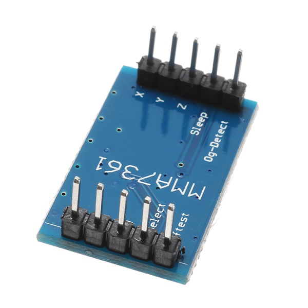
  • Standard 2.54mm (100mil) pin spacing for easy breadboard and PCB integration.

Out of stock

Description

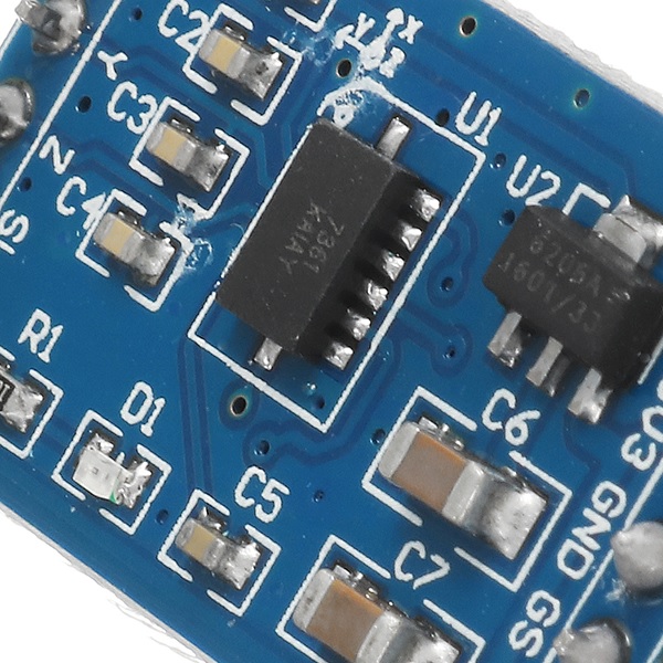
The MMA7361 module integrates a low-cost, miniaturized capacitive MEMS accelerometer, designed as a functional replacement for the older MMA7260. It measures static acceleration (gravity) for tilt sensing and dynamic acceleration for motion detection across three axes. The onboard RT9161 low-dropout regulator provides stable operation from noisy 5V or 3.3V power supplies, making it suitable for embedded systems and portable devices.

Range selection between ±1.5g (800 mV/g sensitivity) and ±6g is configurable via a digital logic pin or onboard resistor, offering flexibility for different measurement precision requirements. The module outputs an analog voltage for each axis (X, Y, Z), which can be read directly by a microcontroller’s ADC inputs. Its low current draw and fast wake-up time make it ideal for battery-powered IoT projects and motion-activated systems.

Key Features

  • MMA7361L 3-axis capacitive accelerometer with g-select functionality.
  • Onboard RT9161 LDO regulator ensures stable 3.3V operation from 5V input.
  • Low noise analog signal paths for each measurement axis.
  • Compact PCB design (28mm x 17mm) with standard interface headers.
  • Optimized for high-noise power supply environments common in motor control or digital systems.
  • Durable construction with soldered IC and passive components.

Applications

  • Tilt sensing and inclination measurement for robotics and platform leveling.
  • Motion detection and impact monitoring in wearable devices and sports equipment.
  • Vibration analysis and simple condition monitoring for industrial machinery.
  • Input for gesture recognition and activity tracking in consumer electronics.
  • Low-power orientation sensing for IoT sensor nodes and remote monitoring systems.

Technical Specifications

Sensor ICMMA7361L
Measurement Axes3 (X, Y, Z)
Selectable Ranges±1.5g, ±6g
Sensitivity (±1.5g)800 mV/g
Supply Voltage3.3V to 5V DC
Active Current400 µA
Sleep Current3 µA
Enable Response Time0.5 ms
Output TypeAnalog Voltage (per axis)
Onboard RegulatorRT9161 LDO
Operating Temperature-40°C to +85°C (IC spec)
Module Dimensions (LxW)28 mm x 17 mm
Module Weight3 g
Pin Pitch2.54 mm (100 mil)

Frequently Asked Questions

What is the difference between the ±1.5g and ±6g ranges, and how do I select them?

The ±1.5g range offers higher sensitivity (800 mV/g) for precise tilt or low-motion applications, while the ±6g range is for higher acceleration events where signal clipping must be avoided. Selection is typically done by connecting the g-select pin on the module to logic HIGH (VCC) for ±1.5g or logic LOW (GND) for ±6g. Some modules may have a solder Jumper or resistor for permanent configuration.

Can I power this module directly from a 5V Arduino pin?

Yes. The module's onboard RT9161 LDO regulator safely steps down a 5V input to the 3.3V required by the MMA7361 sensor IC. You can connect VCC to the Arduino's 5V pin. Ensure the ground (GND) pins are connected, and note that the analog outputs will be relative to the module's 3.3V logic level.

How do I read the sensor data with a microcontroller like an Arduino?

Connect the module's X, Y, and Z analog output pins to three separate ADC inputs on your microcontroller. In your code, read the analog voltage from each pin. To convert the reading to acceleration in 'g', use the formula: Acceleration (g) = (ADC_Reading / ADC_Resolution * Vref) / Sensitivity. For the ±1.5g range with 800 mV/g sensitivity and a 3.3V reference, Sensitivity is 0.8 V/g.

What is the purpose of the sleep (EN) pin?

The enable (EN) pin puts the MMA7361 IC into a low-power sleep mode (3 µA) when pulled low, drastically reducing current consumption for battery-powered applications. When pulled high, the sensor activates with a fast 0.5 ms response time. If not used, this pin should typically be connected to VCC to keep the sensor active.

Package Includes

  • 1 x MMA7361 Accelerometer Module

Additional Information

Weight 0.003 kg
Dimensions 2.8 × 1.7 cm