SKU: IOWC-1404
📋 GST Invoice Available

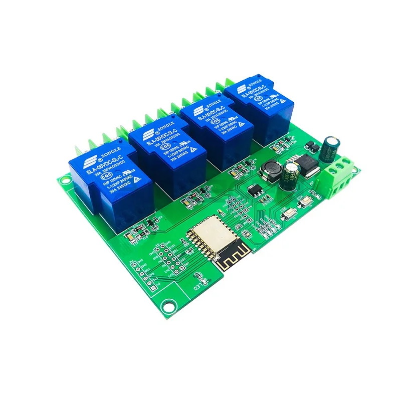
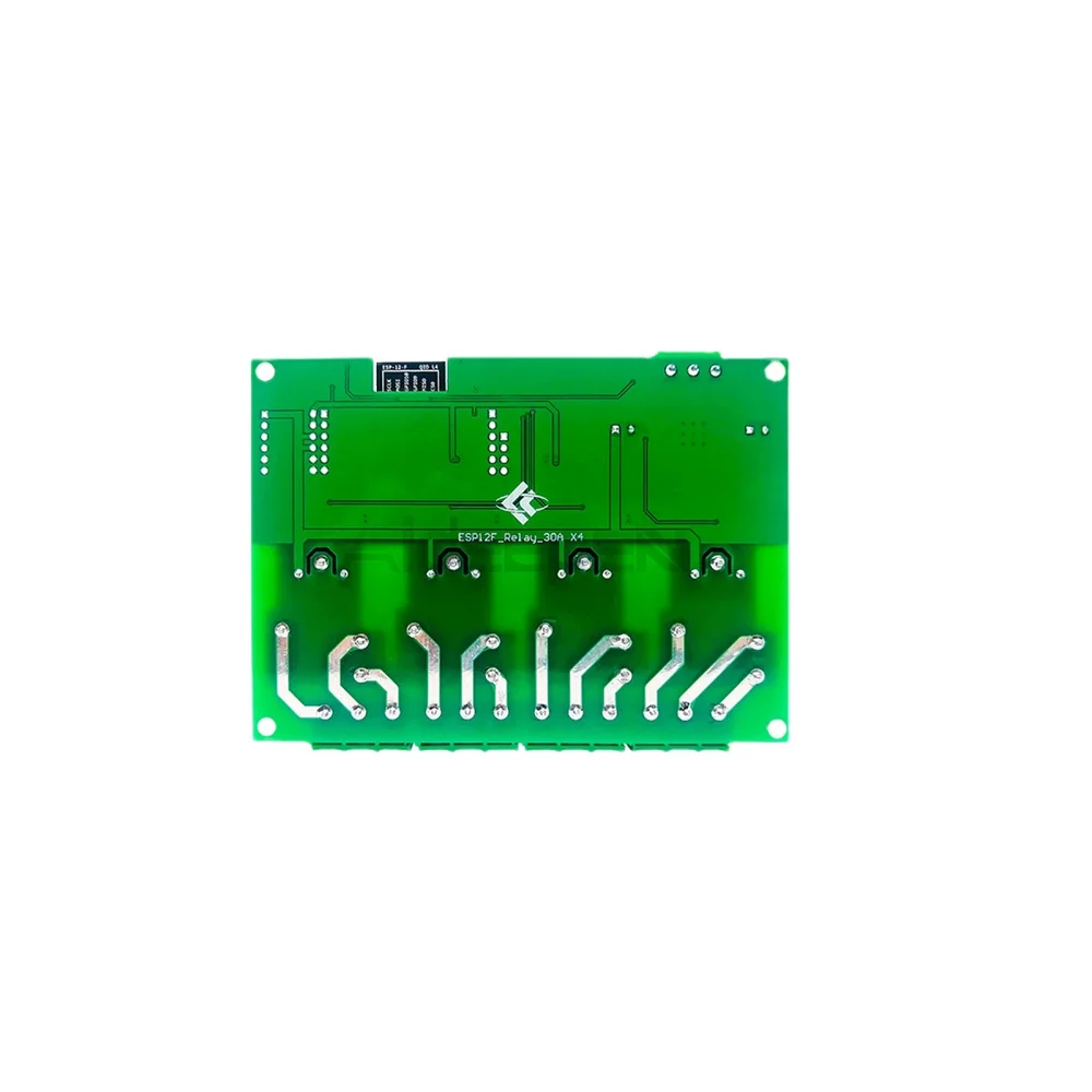
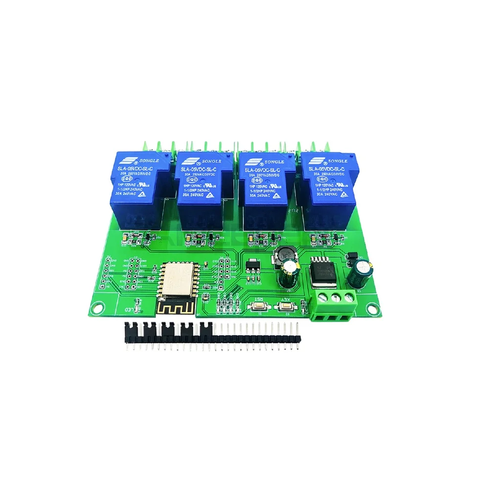
ESP8266 ESP-12F 4-Channel Relay Module DC7-28V/5V 30A

₹1,099.00 (Inclusive of all taxes)
Out of Stock

This ESP8266-based 4-channel relay module integrates an ESP-12F Wi-Fi module for wireless control of high-power AC/DC loads up to 30A, supporting Arduino IDE development and a wide DC7-28V/5V power input.

Features

  • Integrated ESP-12F Wi-Fi module with 4MB Flash for OTA updates and Arduino IDE/MicroPython development.
  • Four high-current relay outputs rated for 30A at 5V, suitable for switching loads up to AC 250V or DC 30V.
  • Wide-range power supply accepts DC 7-28V or standard 5V inputs, ideal for 12V/24V industrial and 5V USB applications.
  • All GPIOs, UART, and program download ports are broken out for secondary development and external sensor integration.
  • Onboard reset button, programmable tactile key, and status LEDs for relay operation and Wi-Fi connectivity indication.

Out of stock

Description

This development board merges the popular ESP8266 Wi-Fi SoC with robust relay control, creating a ready-made node for smart home automation and industrial IoT. The onboard ESP-12F module provides full 802.11 b/g/n connectivity and is pre-configured with accessible I/O pins, enabling direct firmware flashing via the exposed serial UART using the Arduino IDE or ESP8266 SDK.

The module’s power design is flexible, accepting a broad 7-28V DC input range commonly found in automotive and security systems, or a standard 5V USB supply for prototyping. Each of the four relays is rated for 30A, allowing direct control of high-power devices like motors, solenoids, and lighting without requiring an external driver circuit. The board includes necessary indicators and user inputs for system status and manual override functionality.

Key Features

  • ESP-12F core provides embedded Wi-Fi networking with TCP/IP stack and full GPIO access.
  • High-current relay outputs enable direct switching of AC mains or DC power loads.
  • Dual power input range (7-28V DC or 5V) offers flexibility for various deployment scenarios.
  • All microcontroller I/O ports and the program download UART are accessible via pin headers.
  • Includes a hardware reset button and a user-programmable tactile key for manual control.
  • Onboard LEDs indicate power status, relay state, and provide a user-controllable GPIO indicator.
  • Pre-flashed with AT command firmware and includes Arduino reference code for rapid application development.
  • Compact PCB design integrates relay drivers, voltage regulation, and ESP8266 in a single unit.

Applications

  • Smart home automation for lighting, fans, and appliance control via Wi-Fi or MQTT.
  • Industrial IoT (IIoT) for remote switching of motors, pumps, and solenoid valves.
  • DIY security systems to control door locks, sirens, or garage doors.
  • Agricultural automation for irrigation valves and greenhouse equipment.
  • Prototyping and educational projects for learning embedded systems and wireless control.

Technical Specifications

Microcontroller/SoCESP8266 (ESP-12F Module)
Wireless ProtocolWi-Fi 802.11 b/g/n
Relay Channels4
Relay Rating5V DC, 30A per channel
Max Load VoltageAC 250V / DC 30V
Supply VoltageDC 7-28V or 5V
Flash Memory4 MB
InterfacesExposed GPIO, UART (Tx/Rx), Program Download Port
User InterfaceReset Button, Programmable Key, Power/Relay/User LEDs
Development PlatformArduino IDE, ESP8266 SDK, MicroPython

Frequently Asked Questions

How do I program this ESP8266 relay board using the Arduino IDE?

Connect the board's Tx, Rx, GND, and 5V pins to a USB-to-Serial adapter. Ground the GPIO0 pin during power-up to enter flash mode, then select 'NodeMCU 1.0' board in Arduino IDE and upload your sketch. After programming, disconnect GPIO0 from ground and reset the board to run your application, controlling relays via digitalWrite commands on the assigned GPIO pins.

What is the maximum load I can control with each relay channel?

Each relay is rated for 30A at 5V DC coil voltage. The relay contacts can switch loads up to AC 250V or DC 30V. Ensure your load's inrush current does not exceed 30A. For inductive loads like motors, use a snubber circuit or derate the current to prolong relay life and prevent contact welding from voltage spikes.

Can I power this module with a 12V or 24V DC power supply?

Yes, the board's wide-input voltage regulator accepts DC 7V to 28V. You can directly use a 12V wall adapter, a 24V industrial power supply, or a car battery. Ensure your power source can provide sufficient current for both the ESP8266 and the relay coils, especially when multiple relays are activated simultaneously.

Package Includes

  • 1 x ESP8266 Wi-Fi 4-Channel Relay Development Board

Additional Information

Weight 0.2 kg
Dimensions 9 × 9 × 4 cm