SKU: IOWC-1409
📋 GST Invoice Available

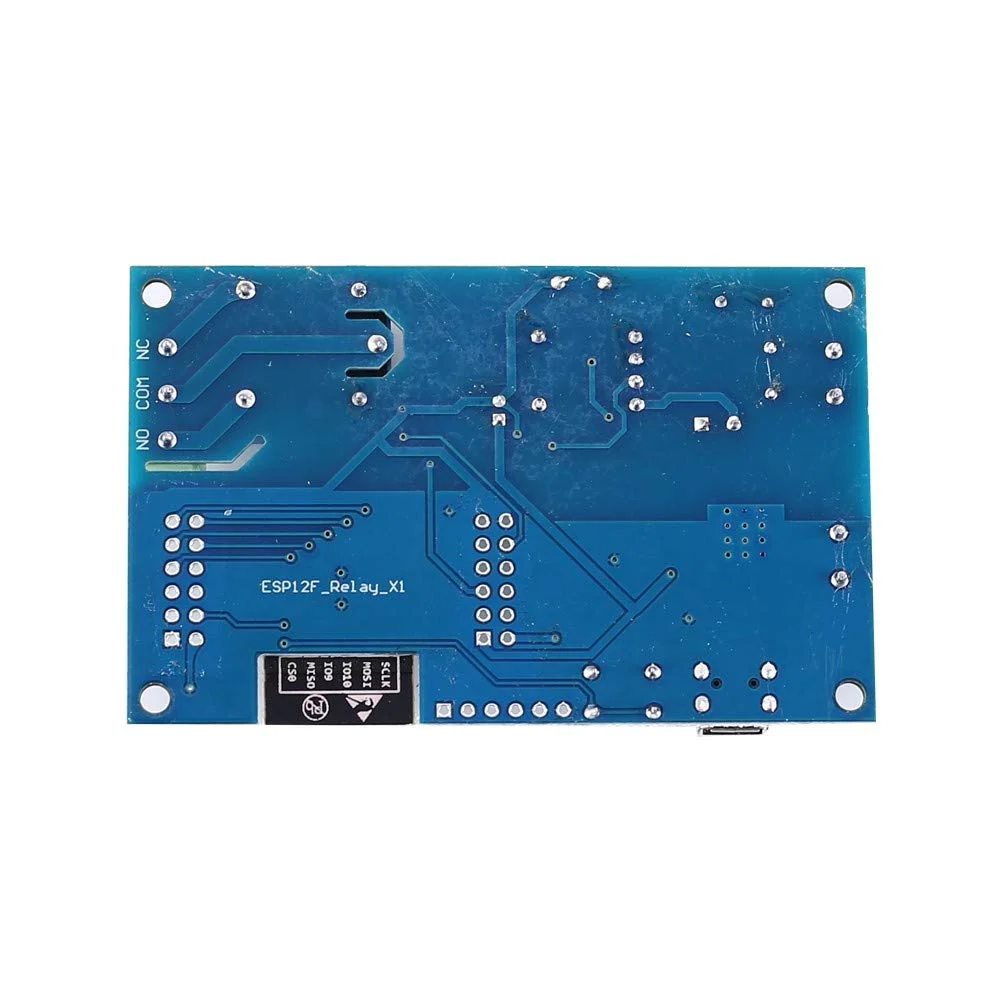
ESP8266 ESP-12F Wi-Fi Relay Module w/ AC-DC Power Supply

₹709.00 (Inclusive of all taxes)
Out of Stock

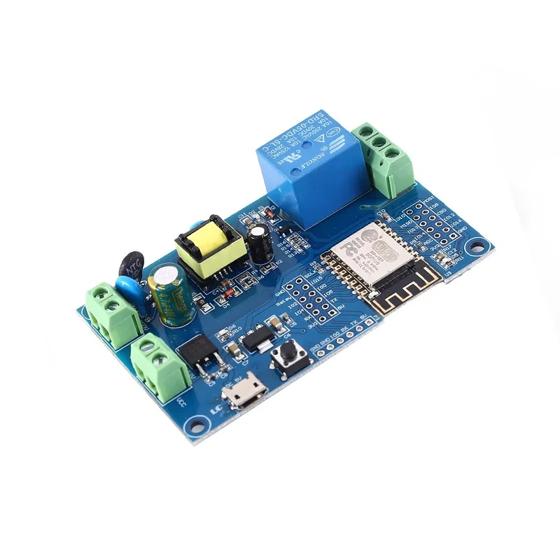
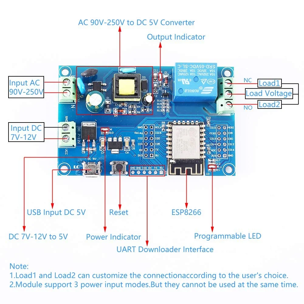
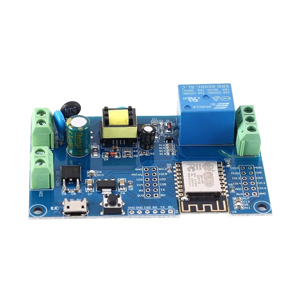
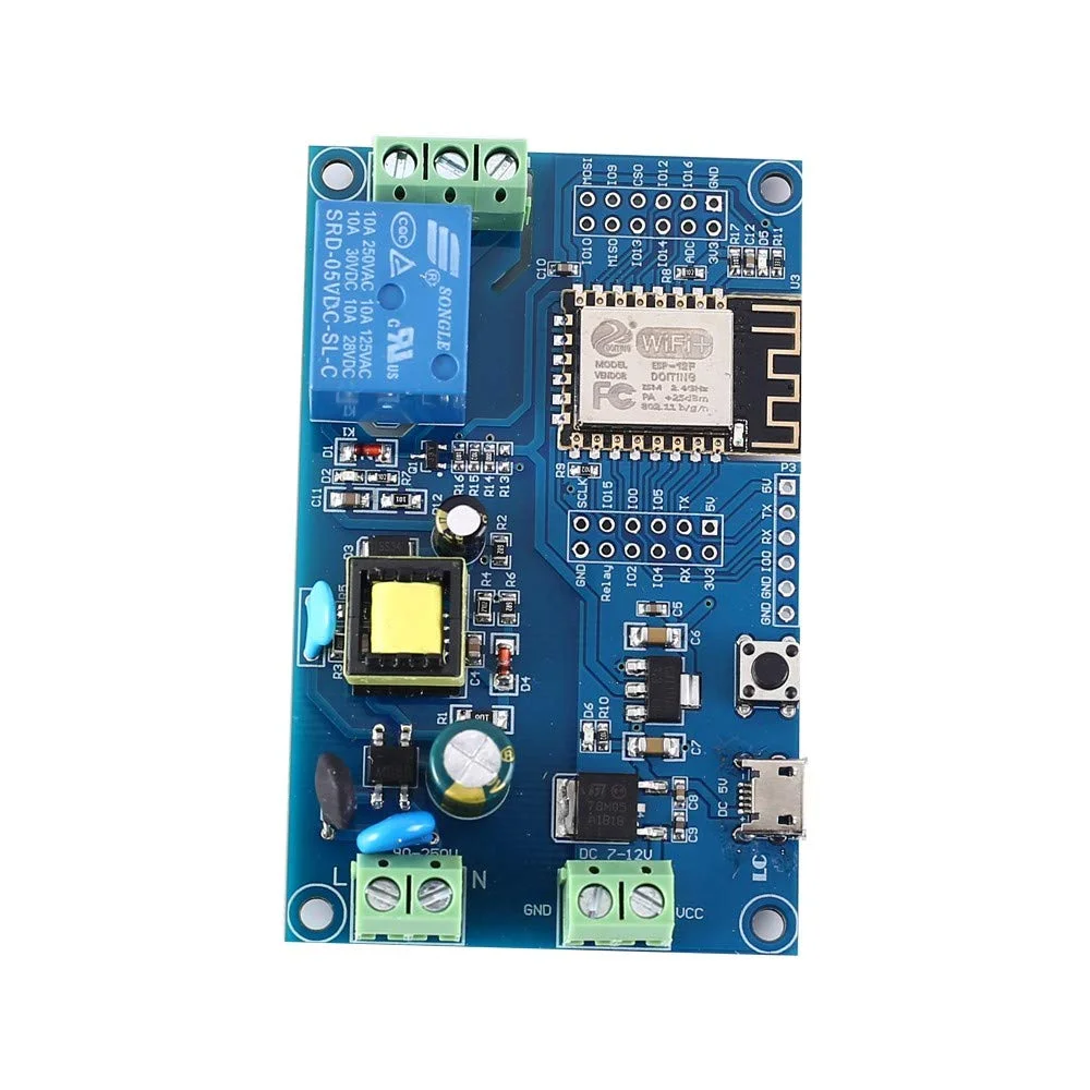
This ESP8266-based Wi-Fi relay development board integrates an ESP-12F module and a 1-channel 5V relay, supporting power input from AC 90-250V, DC 7-28V, or USB 5V for versatile smart home and industrial control applications.

Features

  • Onboard ESP-12F Wi-Fi module with 4MB flash for Arduino IDE or Eclipse development.
  • Integrated single-channel 5V relay for switching loads up to AC 250V or DC 30V.
  • Flexible power supply: AC 90-250V, DC 7-28V, or USB 5V input via onboard AC-DC converter.
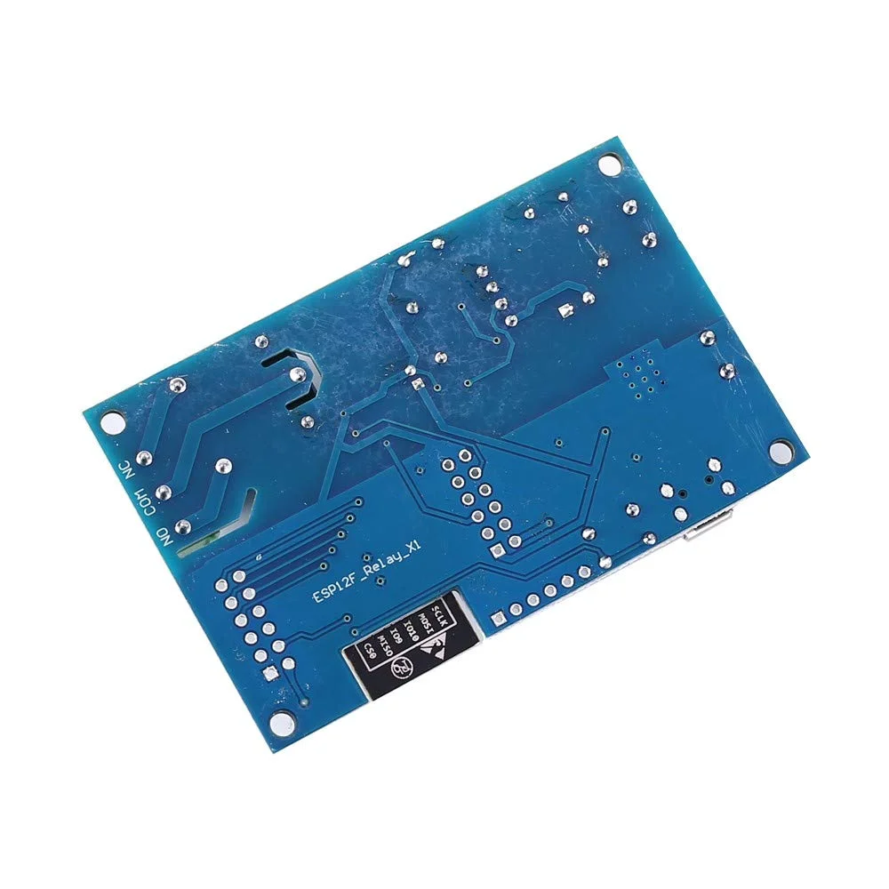
  • Full I/O and UART programming port breakout for easy firmware flashing and secondary development.
  • Includes programmable LED, relay status indicator, and Wi-Fi module reset button.

Out of stock

Description

This development board combines the popular ESP8266 Wi-Fi SoC with a robust relay output, designed for direct integration into mains-powered systems. The onboard ESP-12F module provides reliable 2.4GHz Wi-Fi connectivity and is pre-configured with a 4MB flash memory, enabling over-the-air (OTA) updates and complex firmware logic. The integrated AC-DC switching power supply eliminates the need for an external converter, allowing the board to be powered directly from wall outlets or a wide range of DC sources.

The board is engineered for smart home automation, industrial control, and IoT prototyping. All GPIO pins from the ESP-12F are broken out, alongside a dedicated UART serial port for programming and debugging. This makes it suitable for developers using the Arduino core for ESP8266 or the ESP-IDF framework to create custom firmware for remote switching, sensor-triggered actions, or integration with platforms like Home Assistant or MQTT brokers.

Key Features

  • ESP8266-based Wi-Fi control with ESP-12F module for reliable 2.4GHz connectivity.
  • Single-pole relay output capable of switching high-voltage AC/DC loads.
  • Universal power input via integrated switching regulator (AC/DC/USB).
  • Full pin-header breakout for all ESP-12F GPIOs and serial programming interface.
  • Onboard status LEDs for power, Wi-Fi activity, and relay state.
  • Physical reset button for quick Wi-Fi module reboot and recovery.
  • Compatible with Arduino IDE, PlatformIO, and ESP8266 RTOS SDK for flexible development.
  • Compact form factor designed for enclosure mounting in end-use applications.

Applications

  • Smart home automation for lighting, fans, or appliance control.
  • Industrial IoT (IIoT) for remote switching of machinery or pumps.
  • DIY projects for garage door openers, irrigation systems, or security devices.
  • Energy management systems for monitoring and controlling power outlets.
  • Prototyping and educational tools for learning IoT and embedded systems.

Technical Specifications

Microcontroller/SoCESP8266 (ESP-12F Module)
Wireless ProtocolWi-Fi 802.11 b/g/n
Flash Memory4 MB
Relay Channels1 (5V Coil)
Load RatingAC 250V / DC 30V
Supply VoltageAC 90-250V, DC 7-28V, USB 5V
InterfacesGPIO Headers, UART (Programming)
IndicatorsPower LED, Programmable LED, Relay Status LED
Development SupportArduino IDE, Eclipse, AT Commands
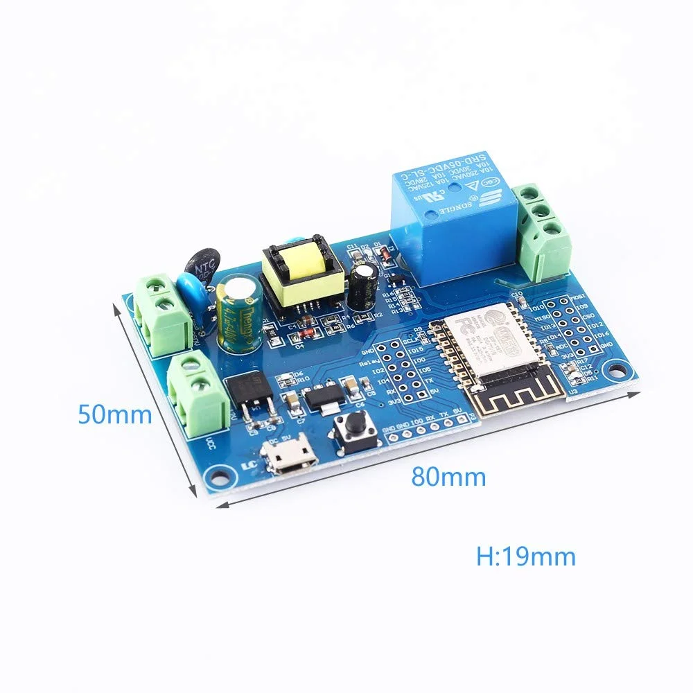
Dimensions (Shipping)6 x 3 x 2 cm

Frequently Asked Questions

How do I program this ESP8266 relay board using the Arduino IDE?

Connect the board's serial programming header (TX, RX, GPIO0, RST, VCC, GND) to a USB-to-serial adapter. In the Arduino IDE, install the ESP8266 board package via the Boards Manager. Select 'Generic ESP8266 Module' as the board, set the correct COM port, and choose the upload speed (usually 115200 baud). Hold the GPIO0 pin low during reset to enter flash mode before uploading your sketch to control the relay via Wi-Fi.

What are the power supply requirements and how do I connect AC mains?

The board accepts three input types: AC 90-250V via the terminal block, DC 7-28V via the same block or a DC jack, or USB 5V. For AC mains, connect the Live and Neutral wires securely to the labeled screw terminals. Ensure the total load on the relay does not exceed its 10A/250V AC rating. The onboard switching regulator provides stable 3.3V to the ESP-12F module. Always follow local electrical codes when wiring high-voltage circuits.

Can I use this board with MQTT or Home Assistant for smart home integration?

Yes. After flashing firmware via Arduino IDE, you can program the ESP8266 to connect to your local Wi-Fi network and communicate with an MQTT broker. Use libraries like PubSubClient to publish relay status and subscribe to control topics. For Home Assistant, configure an MQTT switch entity using the board's published topics. Alternatively, use ESPHome to create a custom firmware that natively integrates with Home Assistant via its API, providing automatic discovery and a user-friendly interface.

What is the purpose of the onboard LEDs and how do I use the programmable LED?

The board has three LEDs: a red power indicator, a blue relay status light, and a green programmable LED connected to a GPIO pin (often GPIO2). The power LED lights when the board is powered. The relay LED indicates the relay's coil state (ON/OFF). The programmable green LED can be controlled by your code for visual feedback, such as indicating Wi-Fi connection status, a timer countdown, or a system error. Refer to the pinout diagram to identify the exact GPIO for this LED in your sketches.

Package Includes

  • 1 x AC/DC Power ESP8266 Wi-Fi Single Relay ESP-12F Development Board

Additional Information

Weight 0.05 kg
Dimensions 3 × 6 × 2 cm