SKU: IOWC-1332
📋 GST Invoice Available

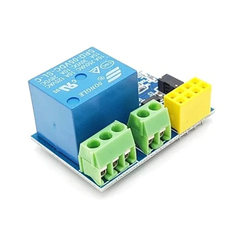
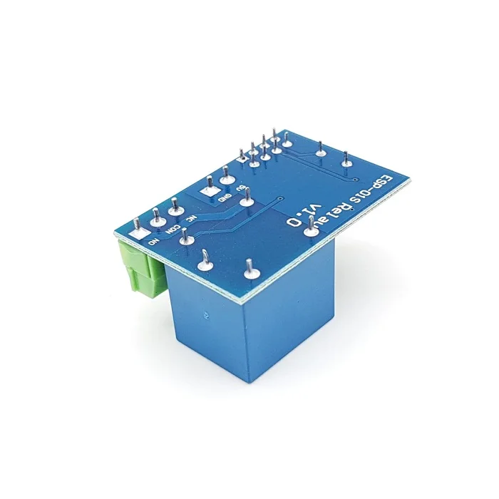
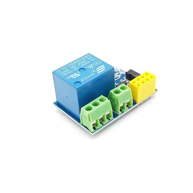
ESP8266 ESP-01S WiFi Relay Module w/ 10A Relay

₹89.00 (Inclusive of all taxes)
Out of Stock

The ESP8266 ESP-01S WiFi Relay Module integrates a 2.4GHz ESP8266 SoC with a 10A relay, enabling remote control of AC appliances via Wi-Fi for Arduino IDE and ESP-AT command firmware projects.

Features

  • ESP8266-Powered Wi-Fi Control: Features the ESP8266EX SoC with integrated 2.4GHz Wi-Fi (802.11 b/g/n) for seamless connectivity to your local network, enabling remote switching via web interfaces or MQTT.
  • High-Capacity Relay: Incorporates a robust single-pole relay rated for 250VAC/10A, suitable for safely controlling lights, fans, and small appliances directly from your smart home system.
  • Compact & Developer-Friendly: Combines the ESP-01S module footprint with a relay in a compact board, offering accessible GPIO0 and GPIO2 pins for relay control and status LEDs, simplifying integration.
  • Low-Voltage Operation: Powered by a stable 3.3V DC supply, making it compatible with common USB power banks, benchtop supplies, or regulated power modules for portable or embedded installations.

Out of stock

Description

The ESP8266 ESP-01S Relay Module is a purpose-built IoT control node designed for developers and makers creating smart home automation and remote switching solutions. It pairs the proven ESP8266 microcontroller, with its integrated Wi-Fi stack and processing capabilities, with a mechanical relay capable of handling significant AC loads. This integration allows for the creation of Wi-Fi-enabled smart sockets, light switches, and appliance controllers without the need for separate relay driver circuits.

Architecturally, the module leverages the ESP8266’s GPIO0 and GPIO2 for direct relay coil control and status indication, while the onboard UART (up to 115200 bps) facilitates serial communication for debugging or AT command control. The design emphasizes ease of use, with a standard 4-pin header for programming via a USB-to-serial adapter, enabling firmware development in popular environments like the Arduino IDE or ESP8266 SDK. Its compact form factor and 3.3V logic level make it a versatile component for embedding into enclosures or existing electrical setups.

Key Features

  • Integrated Wi-Fi & Relay: Combines the full ESP8266 Wi-Fi networking stack with a high-current relay on a single board, eliminating external wiring between a separate module and relay driver.
  • Remote Appliance Control: Enables secure over-the-air control of connected AC or DC devices via local network web servers, cloud platforms (like Blynk, SinricPro), or MQTT brokers.
  • Arduino & AT Command Compatible: Fully programmable using the Arduino Core for ESP8266 for custom logic or can be used as a simple Wi-Fi-to-serial relay using pre-loaded AT command firmware.
  • Compact Form Factor: The small board dimensions allow for direct installation inside standard electrical junction boxes or project enclosures for a clean, professional finish.
  • Direct GPIO Control: Provides straightforward access to the relay control pin (typically GPIO0) and an optional status LED pin (GPIO2), simplifying the code for toggling the relay state.
  • Serial Debugging Interface: Includes TX/RX pins for serial communication, allowing for real-time debugging, log output, and configuration via AT commands during development.

Applications

  • Smart Home Automation: Core component for building Wi-Fi-controlled smart sockets, light switches, and appliance timers for lamps, fans, or coffee makers.
  • IoT Prototyping & Makerspaces: Ideal for educational projects and prototypes demonstrating remote control, integrating with platforms like Home Assistant, Node-RED, or IFTTT.
  • Energy Management Systems: Can be used in DIY energy-saving setups to schedule or remotely power down non-essential devices based on occupancy or time of day.
  • Security & Safety Projects: Enables remote activation of sirens, alarms, or indicator lights as part of a simple DIY security or notification system.

Technical Specifications

Microcontroller/SoCESP8266EX (Tensilica L106 32-bit RISC)
Wireless ProtocolsWi-Fi 802.11 b/g/n (2.4 GHz)
Relay SpecificationSingle Relay, 250VAC / 10A, Normally Open (NO)
Supply Voltage3.3V DC
Control InterfacesGPIO0 (Relay Control), GPIO2 (Status LED)
Serial CommunicationUART, up to 115200 bps
Programming Interface4-pin header (VCC, GND, TX, RX, GPIO0)
Dimensions (Shipping)Approx. 10 x 6 x 3 cm

Frequently Asked Questions

How do I program this ESP8266 relay module using the Arduino IDE?

Connect the module's VCC (3.3V), GND, TX, and RX pins to a USB-to-serial adapter (like FTDI). Ensure GPIO0 is pulled to GND during power-up to enter flashing mode. In the Arduino IDE, select 'Generic ESP8266 Module' as the board, choose the correct COM port, and upload your sketch. Remember to set the baud rate to 115200 for serial communication. After programming, GPIO0 can be used as a digital output to control the relay coil.

What is the maximum load the onboard relay can switch?

The integrated single-pole relay is rated for a maximum of 10 Amperes at 250 Volts Alternating Current (AC). This makes it suitable for controlling common household appliances like lamps, fans, or small heaters. For inductive loads like motors, consider derating or using a snubber circuit to protect the relay contacts from arcing. Always ensure your wiring and enclosure meet local electrical safety standards for mains voltage projects.

Can I power this module directly from a 5V USB port?

No, the module requires a stable 3.3V DC power supply. Applying 5V directly to the VCC pin will likely damage the ESP8266 chip. You must use a 3.3V regulator, such as an AMS1117, or a dedicated 3.3V power source. If using a USB-to-serial adapter for programming, ensure it provides a 3.3V output on its VCC pin. The relay coil itself is also driven by 3.3V, so the entire module operates on this single voltage rail.

Which GPIO pins are used to control the relay and LED on this board?

Typically, GPIO0 is connected to the relay control circuit; setting it HIGH or LOW activates or deactivates the relay. GPIO2 is often connected to an onboard status LED, providing visual feedback. These assignments are defined by the board's design and your firmware. When writing code, you must configure these pins as outputs. Note that GPIO0 also has a special function during boot, so its initial state can affect the module's startup mode.

Package Includes

  • 1 x ESP8266 ESP-01S WiFi Relay Module

Additional Information

Weight 0.008 kg
Dimensions 6 × 10 × 3 cm