SKU: IOWC-0860
📋 GST Invoice Available

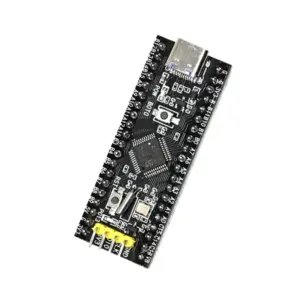
SIM800C GSM GPRS Module Development Board 5V/3.3V TTL w/ IPEX Antenna

₹439.00 (Inclusive of all taxes)
Out of Stock

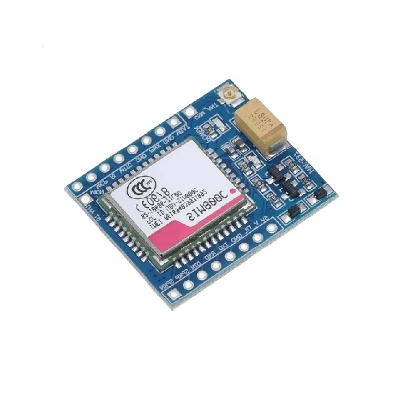
The SIM800C GSM GPRS Module Development Board provides a 5V/3.3V TTL-level interface for integrating quad-band GSM/GPRS and Bluetooth connectivity into STM32, C51, or Arduino-based IoT projects. It features an IPEX antenna connector for reliable network registration and data transmission.

Features

  • SIM800C quad-band GSM/GPRS module for global 2G network connectivity (850/900/1800/1900MHz).
  • Dual 5V/3.3V TTL logic level compatibility for direct interfacing with 3.3V and 5V microcontrollers.
  • Integrated Bluetooth 4.0 for short-range wireless data transfer and device control.
  • Onboard IPEX antenna connector for improved signal reception and transmission range.
  • Comprehensive audio and control pins (SPK, MIC, DTR, PWR, RI) for voice calls and SMS alerts.

Out of stock

Description

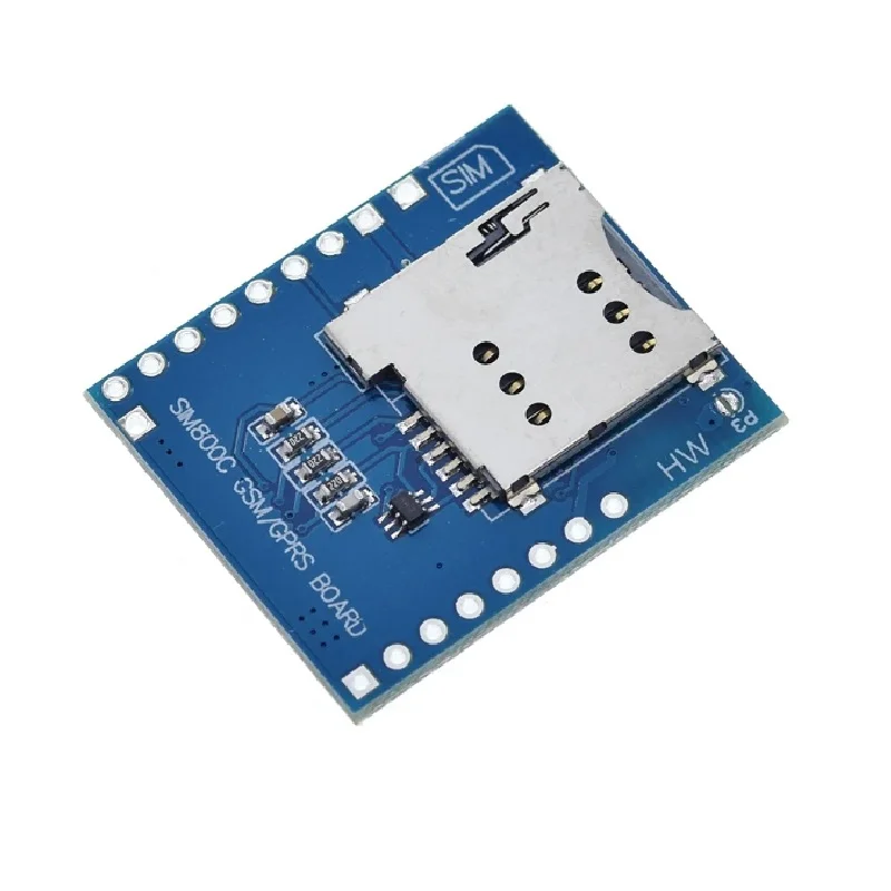
This development board hosts the SIM800C cellular module, a widely adopted 2G solution for machine-to-machine (M2M) communication. It provides a complete breakout for the module’s serial UART (TXD/RXD), power management (VBAT, VRTC), and audio interfaces, simplifying integration into embedded systems. The board includes a logic level converter, allowing safe connection to both 3.3V and 5V microcontroller GPIOs.

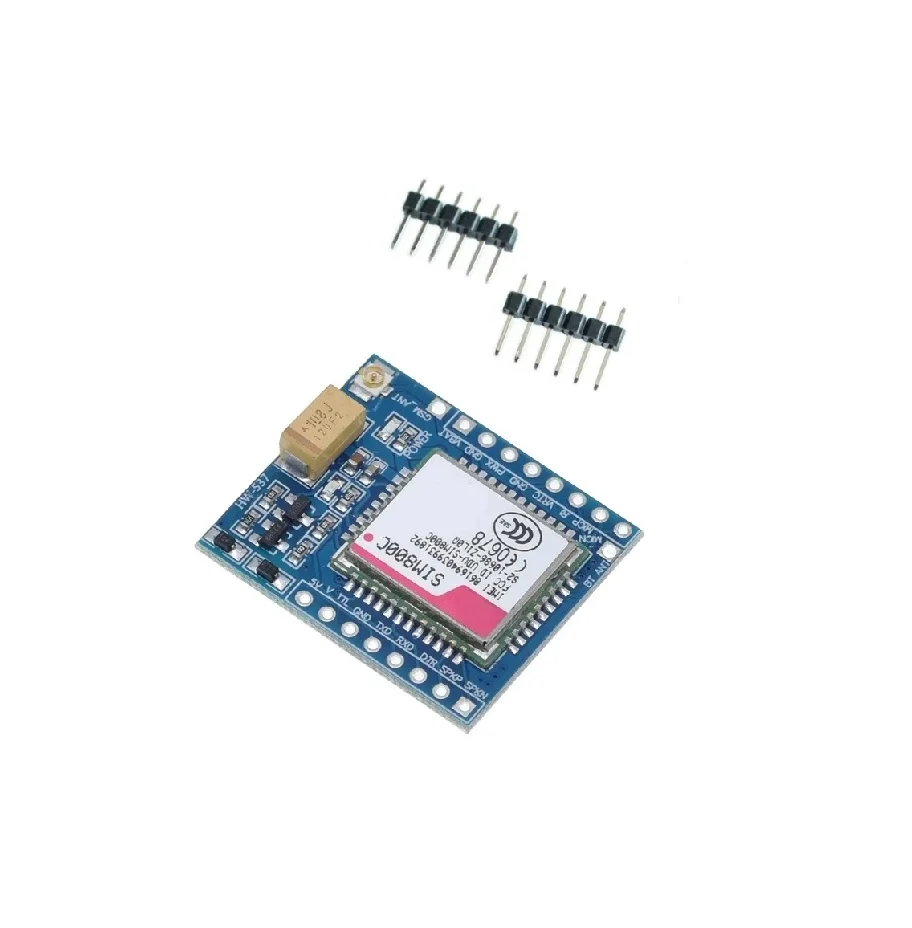
Designed for low-power IoT deployments, the SIM800C supports GPRS data transmission, SMS messaging, and voice calls. The unwelded pin header design offers flexibility for direct soldering or cable connection, catering to custom enclosure requirements. Its compact SMD footprint makes it suitable for space-constrained applications like remote telemetry, asset trackers, and industrial alarm systems.

Key Features

  • Quad-band GSM/GPRS (850/900/1800/1900 MHz) for worldwide 2G network compatibility.
  • Integrated Bluetooth 4.0 (BLE) for auxiliary wireless configuration and data exchange.
  • Onboard 5V-to-3.3V level shifter protects SIM800C I/O when connected to 5V microcontroller logic.
  • IPEX antenna port (U.FL) for connecting external high-gain GSM antennas to boost signal strength.
  • Comprehensive breakout includes audio in/out (MICN/P, SPKN/P), power key (PWR), ring indicator (RI), and DTR for sleep control.
  • Supports GPRS Class 12 (85.6 kbps download/upload) for TCP/IP, HTTP, and MQTT protocol data transmission.
  • External VBAT (3.3V-4.4V) and VRTC pins for direct lithium battery connection and RTC backup.
  • Unwelded header pins allow for custom wiring, direct soldering to mainboards, or use with dupont cables.

Applications

  • Remote sensor data logging and telemetry over GPRS networks.
  • SMS-based alarm and notification systems for security or industrial monitoring.
  • Asset tracking and fleet management with periodic location updates.
  • IoT gateway for bridging local sensor networks (e.g., Bluetooth) to the cloud via cellular.
  • Basic voice call and DTMF-controlled devices for vending machines or remote intercoms.

Technical Specifications

Wireless Module/ChipsetSIM800C
Wireless ProtocolsGSM/GPRS (2G), Bluetooth 4.0
Frequency RangeQuad-band GSM: 850/900/1800/1900 MHz
RF Transmit PowerClass 4 (2W) @ 850/900 MHz, Class 1 (1W) @ 1800/1900 MHz
Supply Voltage (Board)5V DC
Module Supply Voltage (VBAT)3.3V to 4.4V
Logic Level3.3V TTL (Module), 5V/3.3V TTL (Board Interface)
InterfacesUART (TXD, RXD), Audio (MIC, SPK), Control (PWR, DTR, RI)
Antenna ConnectorIPEX (U.FL) Female
Operating Temperature-40°C to +85°C (Module)
Dimensions (Board)Approx. 40mm x 30mm (Estimated)

Frequently Asked Questions

How do I power this SIM800C development board and what is the current consumption?

Power the board via the 5V and GND pins. The SIM800C module itself requires 3.3V-4.4V on its VBAT pin, which is supplied by the onboard regulator. During a GSM call, peak current can reach 2A; in GPRS data mode, average current is 200-300mA. Ensure your 5V supply can deliver at least 2A. Use the PWR pin and AT commands to control module power states and minimize sleep current to around 1mA.

How do I connect and program this board with an Arduino or STM32 microcontroller?

Connect the board's TXD (module transmit) to your MCU's RX pin, and RXD (module receive) to your MCU's TX pin. Set your serial communication to 9600 or 115200 baud. Use the V_TTL pin to select 5V or 3.3V logic matching your MCU. Send standard AT commands (e.g., AT, AT+CSQ, AT+CMGS) via serial to control GSM functions. For Bluetooth, use specific AT commands (AT+BT...) for pairing and data transfer. Always include a delay after the PWR key sequence.

What type of antenna should I use and how do I connect it to the IPEX port?

Use a GSM/2G antenna with an IPEX (U.FL) male connector, tuned for 850/900/1800/1900 MHz bands. A 3dBi gain stub antenna is typical. Carefully mate the antenna connector to the board's IPEX port, ensuring a secure click. For permanent installations, consider an external magnetic mount antenna with an IPEX-to-SMA pigtail cable to improve signal strength. Avoid bending the cable sharply near the connector to prevent damage to the delicate center pin.

Package Includes

  • 1 x SIM800C GSM GPRS Module Development Board (Unwelded Headers)

Additional Information

Weight 0.007 kg
Dimensions 6 × 8 × 3 cm