SKU: IOWC-1319
📋 GST Invoice Available

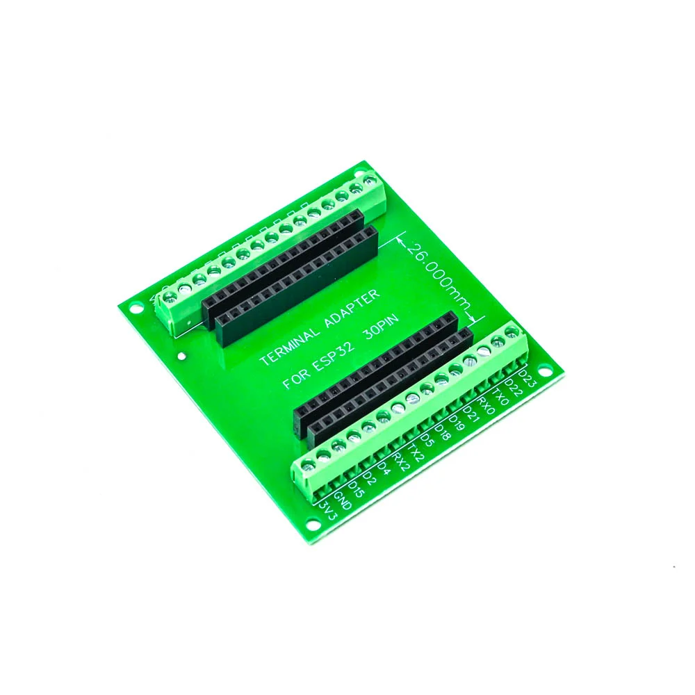
Generic ESP32 Breakout Board 30-Pin Development Module

₹239.00 (Inclusive of all taxes)
Out of Stock

A 30-pin breakout board for the ESP32 microcontroller, providing simplified access to GPIOs and integrated Wi-Fi/Bluetooth for rapid prototyping and development in Arduino IDE or ESP-IDF.

Features

  • 30-pin breakout design simplifies GPIO access for ESP32 prototyping and testing.
  • Features the powerful ESP32 SoC with dual-core processing and integrated Wi-Fi/Bluetooth.
  • Built on a 2-layer FR-4 PCB for reliable electrical performance and durability.
  • Compact form factor ideal for breadboarding and integration into custom enclosures.
  • Direct compatibility with standard ESP32 development workflows and libraries.

Out of stock

Description

The Generic ESP32 Breakout Board is a fundamental development tool that provides a clean, organized interface to the ESP32 microcontroller’s I/O pins. It breaks out the chip’s 30 GPIOs, power rails, and communication buses (UART, SPI, I2C) into a standard pin header layout, eliminating the need for direct soldering to the ESP32 module. This design accelerates circuit prototyping and testing for IoT applications.

Powered by the Espressif ESP32, the board delivers dual-core processing at up to 240 MHz, integrated 802.11 b/g/n Wi-Fi, and Bluetooth 4.2 BR/EDR/BLE. The 2-layer FR-4 PCB ensures signal integrity for both digital and RF circuits. It serves as a versatile foundation for developing connected devices, sensor nodes, and automation controllers, compatible with the Arduino core for ESP32, ESP-IDF, and MicroPython.

Key Features

  • Breaks out 30 GPIO pins from the ESP32 module for easy breadboard and peripheral connection.
  • Enables rapid prototyping by providing direct access to power, ground, and all major communication interfaces.
  • Simplifies firmware development and debugging with a standardized pinout.
  • Compact and lightweight design facilitates integration into proof-of-concept builds and final projects.
  • Compatible with a vast ecosystem of ESP32 libraries, examples, and development frameworks.

Applications

  • Rapid prototyping of IoT devices and smart home automation nodes.
  • Educational tool for learning embedded systems and wireless connectivity.
  • Foundation for building custom sensor hubs, data loggers, and wireless controllers.
  • Testing and development platform for ESP32-based firmware and applications.

Technical Specifications

Microcontroller/SoCEspressif ESP32 (Dual-Core)
Wireless ProtocolsWi-Fi 802.11 b/g/n, Bluetooth 4.2 BR/EDR/BLE
GPIO Pins30
PCB MaterialFR-4
PCB Layers2
ColorGreen
Dimensions (Shipping)13 x 8 x 4 cm

Frequently Asked Questions

What is the primary purpose of this ESP32 breakout board?

This board provides a physical interface to easily connect jumper wires, sensors, and peripherals to the ESP32's GPIO pins. It eliminates the need to solder directly to the compact ESP32 module, making circuit prototyping, testing, and firmware development significantly faster and more convenient for IoT projects.

How do I power this breakout board and what is the voltage requirement?

The board typically accepts a 3.3V DC supply, which should be connected to the 3V3 and GND pins. You can use a regulated 3.3V power supply or a USB-to-serial programmer that provides 3.3V logic. Avoid applying 5V to any GPIO pin, as the ESP32 is a 3.3V device and higher voltages can damage the microcontroller.

Can I program the ESP32 on this breakout board using the Arduino IDE?

Yes, you can program it using the Arduino IDE. You will need an external USB-to-serial programmer (e.g., FTDI board) connected to the board's TX, RX, GPIO0, and EN pins. Install the ESP32 board package via the Boards Manager, select the correct ESP32 model, choose the programmer's COM port, and upload your sketch after putting the board into bootloader mode by holding GPIO0 low during reset.

Package Includes

  • 1 x Green ESP32 Breakout Board

Additional Information

Weight 0.038 kg
Dimensions 13 × 8 × 4 cm