SKU: SBCD-0266
📋 GST Invoice Available

Adafruit 555 PWM Output STEMMA - Adjustable Frequency

₹579.00 (Inclusive of all taxes)
Out of Stock

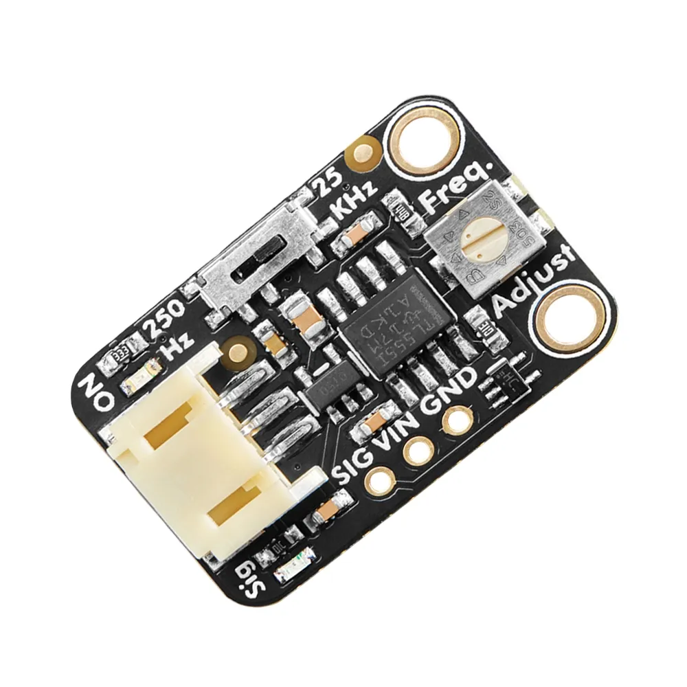
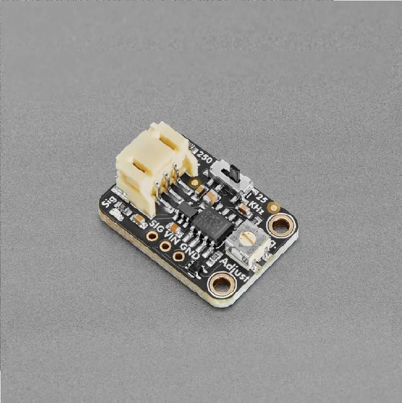
The Adafruit 555 PWM Output STEMMA board provides an adjustable square-wave PWM signal across two selectable frequency ranges, ideal for prototyping and embedded applications. With its 74HC1G04 buffered output and JST PH 2mm connector, it offers simple integration and precise frequency control from 3V to 12VDC systems.

Features

  • Generates adjustable PWM square-wave output with two selectable frequency ranges.
  • Features a 74HC1G04 buffered output capable of sinking/sourcing up to 12.5mA.
  • Equipped with a STEMMA JST PH 2mm connector for solder-free integration and 3V-12VDC operation.
  • Includes an onboard trimmer potentiometer for precise frequency adjustment.

Out of stock

Description

The Adafruit 555 PWM Output STEMMA provides a reliable solution for generating adjustable square-wave PWM signals. This fully-assembled board, based on the classic 555 timer IC, is engineered for straightforward integration into various electronic projects requiring precise frequency control. It eliminates the need for complex discrete component setups, making it suitable for both hobbyists and professional developers.

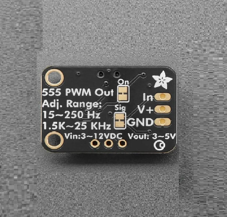
Users can select between two distinct frequency ranges: approximately 1.5 KHz to 25 KHz or 1.5 Hz to 250 Hz, fine-tuned using an onboard trimmer potentiometer. The output is buffered by a 74HC1G04 gate, enabling it to sink or source up to 12.5mA, suitable for driving a range of loads. Powering the board is flexible, accepting 3V to 12VDC, with an internal regulator managing voltage for optimal 555 and buffer operation. Its STEMMA JST PH 2mm connector simplifies connection, promoting quick prototyping and project deployment.

Key Features

  • Generates an adjustable PWM square-wave output signal.
  • Offers two selectable frequency ranges: 1.5 KHz to 25 KHz for higher frequencies, and 1.5 Hz to 250 Hz for lower frequencies.
  • Features a robust DC square wave output driven by a 74HC1G04 buffer.
  • Capable of sinking or sourcing up to 12.5mA, suitable for various loads.
  • Wide operating voltage range from 3V to 12VDC, accommodating diverse power sources.
  • Equipped with an onboard trimmer potentiometer for precise frequency fine-tuning.
  • Designed for ease of use with STEMMA JST PH cable compatibility, requiring no soldering.
  • RoHS compliant, adhering to environmental standards.

Applications

  • Driving piezo buzzers and audio indicators.
  • Generating modulating signals for IR transmitters.
  • Creating clock signals for basic digital circuits.
  • Educational projects involving timing and waveform generation.

Technical Specifications

IC ChipTL555I
Output TypePWM Square Wave
High Frequency Range1.5 KHz - 25 KHz
Low Frequency Range1.5 Hz - 250 Hz
Output Buffer74HC1G04
Output Drive CapabilityUp to 12.5mA (Sink/Source)
Power Supply Voltage3V to 12VDC
Connector TypeSTEMMA JST PH 2mm

Frequently Asked Questions

What power supply voltage does the Adafruit 555 PWM Output STEMMA require?

This board operates on a DC power supply ranging from 3V to 12V. An onboard regulator ensures the internal 555 timer and buffer receive a stable 5V, providing flexibility for integration into various low-voltage embedded systems and battery-powered applications.

How do I adjust the output frequency of this module?

The frequency is adjusted using the onboard trimmer potentiometer. You can also select between two primary frequency ranges (1.5 Hz to 250 Hz or 1.5 KHz to 25 KHz) via a jumper, allowing fine-tuning within the chosen range for specific application requirements.

What is the purpose of the 74HC1G04 buffer on the output?

The 74HC1G04 buffer strengthens the output signal, enabling it to sink or source up to 12.5mA. This buffering prevents the 555 timer itself from being overloaded by external loads, ensuring a clean and stable square-wave output suitable for driving LEDs, small relays, or other digital inputs.

Is this board compatible with standard breadboards or microcontrollers?

Yes, the board's STEMMA JST PH 2mm connector simplifies interfacing with microcontrollers or development boards that support this common connector type, such as many Adafruit or SparkFun products. It can also be easily adapted for breadboard use with appropriate JST PH breakout cables or adapters.

What are the typical uses for the two frequency ranges?

The lower range (1.5 Hz - 250 Hz) is ideal for applications like blinking LEDs, creating slow pulsing effects, or controlling servo motors. The higher range (1.5 KHz - 25 KHz) is suitable for generating audio tones, driving piezo buzzers, or modulating infrared signals for remote control projects.

Package Includes

  • 1 x Adafruit 555 PWM Output STEMMA Board

Additional Information

Weight 0.01 kg
Dimensions 13 × 7 × 2 cm