SKU: IOWC-1895
📋 GST Invoice Available

ESP8266 Adapter Plate Serial Wireless Wi-Fi Module

₹44.00 (Inclusive of all taxes)
Out of Stock

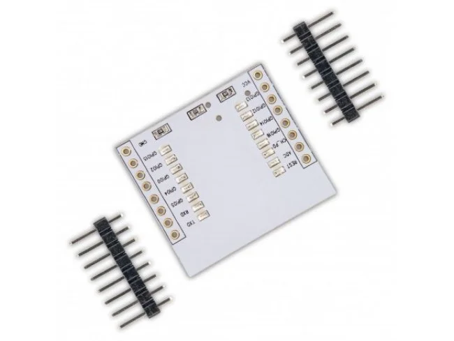
This ESP8266 adapter plate provides a breadboard-friendly breakout for ESP-07, ESP-08, and ESP-12 series SMD Wi-Fi modules, featuring a pre-populated 10K pull-up resistor and a land pattern for an optional 3.3V regulator.

Features

  • Breakout adapter for ESP-07, ESP-08, ESP-12E, and ESP-12F SMD Wi-Fi modules with unfriendly pin pitch.
  • Includes a reserved land pattern for a 3.3V voltage regulator, enabling flexible 4.5V to 9V input via a configurable jumper.
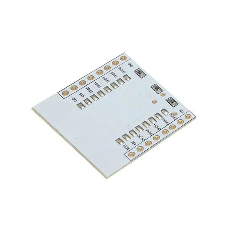
  • Features clear top-layer pinout labels in black and a pre-populated 10K pull-up resistor on the PCB for simplified integration.
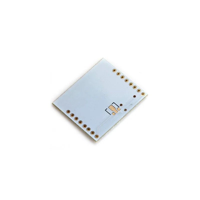
  • Compact 28mm x 31mm white PCB design with standard 2.54mm header spacing for easy prototyping on breadboards or perfboards.

Out of stock

Description

The ESP8266 Adapter Plate is a passive breakout board designed to simplify interfacing with compact ESP8266 SMD modules like the ESP-07, ESP-08, and ESP-12 series. These modules feature a fine-pitch SMD footprint that is difficult to solder directly to prototyping boards. This adapter provides a standard 2.54mm pin header layout, bringing all GPIO, power, and serial pins to a breadboard-friendly format.

The board includes intelligent power management features, such as a land pattern for an optional 3.3V linear regulator and a configurable 0-ohm resistor (R2) to select between direct 3.3V input or a higher 4.5V-9V input range. The clear silkscreen labeling and pre-installed 10K pull-up resistor accelerate development cycles for IoT projects, wireless sensors, and smart home devices using the Arduino IDE or ESP8266 SDK.

Key Features

  • Universal breakout for ESP-07, ESP-08, ESP-12E, and ESP-12F ESP8266 SMD Wi-Fi modules.
  • Integrated land pattern for adding a 3.3V voltage regulator (not included) for wider input voltage flexibility.
  • Configurable power path via a 0-ohm jumper resistor (R2) to bypass the regulator for direct 3.3V operation.
  • Pre-populated 10K pull-up resistor on the PCB for reliable signal conditioning.
  • Clear top-layer pinout markings in black for easy identification of GPIO, UART, and power pins.
  • Standard 2.54mm pin header spacing compatible with breadboards, perfboards, and Dupont cables.
  • 1.6mm thick white FR4 PCB for durability and clear visual inspection of solder joints.

Applications

  • Prototyping and development with ESP8266 SMD modules on breadboards.
  • Integrating ESP-12 series modules into custom IoT sensor nodes and smart home devices.
  • Creating wireless serial bridges or Wi-Fi gateways for Arduino or microcontroller projects.
  • Educational and maker projects requiring a reliable interface to compact ESP8266 Wi-Fi chips.

Technical Specifications

Item TypeWi-Fi Module Adapter/Breakout
Compatible ModulesESP-07, ESP-08, ESP-12E, ESP-12F (ESP8266 Based)
PCB ColorWhite
PCB Thickness1.6 mm
Dimensions (L x W)31 mm x 28 mm
Weight4 g
Key FeatureLand pattern for 3.3V regulator, 10K pull-up resistor

Frequently Asked Questions

Which ESP8266 modules are compatible with this adapter plate?

This adapter plate is designed for ESP8266-based SMD modules with a specific footprint, including the ESP-07, ESP-08, ESP-12E, and ESP-12F. You solder the module directly onto the pads on the top of the PCB. The board then breaks out all pins, including GPIOs, UART, VCC, and GND, to standard 2.54mm male headers for easy connection to a breadboard or other circuitry.

How do I power the module using this adapter plate?

You have two options. For direct 3.3V operation, ensure the 0-ohm resistor R2 is soldered to connect the VCC pin directly to the module's 3.3V input. To use a wider 4.5V to 9V input range, desolder R2 and solder a 3.3V linear regulator (AMS1117 type) into the provided land pattern. The VCC pin then becomes your higher voltage input, and the regulator outputs a stable 3.3V to the Wi-Fi module.

What is the purpose of the pre-populated 10K resistor on the PCB?

The 10K resistor is a pull-up resistor installed on the PCB. It is typically connected to a critical signal line, such as the ESP8266's CH_PD (chip enable) or GPIO0 (boot mode), to ensure it starts in the correct state by default. This simplifies your external wiring, as you may not need to add an external resistor for basic operation, allowing for a cleaner and faster prototyping setup.

Package Includes

  • 1 x ESP8266 Adapter Plate

Additional Information

Weight 0.004 kg
Dimensions 3.1 × 2.8 cm