SKU: IOWC-1301
📋 GST Invoice Available

Waveshare ESP32-S3 A7670E LTE 4G Development Board w/ Camera

₹5,209.00 (Inclusive of all taxes)
Out of Stock

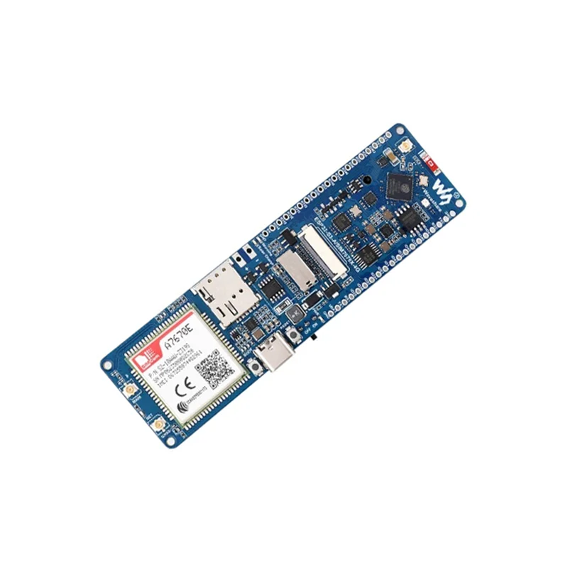
The Waveshare ESP32-S3 A7670E LTE 4G Development Board is an all-in-one IoT platform integrating a dual-core ESP32-S3R2 for Wi-Fi/Bluetooth LE, an A7670E 4G Cat-1 cellular module for global LTE/2G connectivity, and an OV2640 camera. It supports multi-GNSS positioning, battery/solar power management, and is ideal for Arduino IDE, ESP-IDF, or MicroPython development of remote monitoring and portable 4G gateway projects.

Features

  • ESP32-S3R2 & A7670E Combo: Combines a 240MHz dual-core Xtensa LX7 processor with 2.4GHz Wi-Fi/Bluetooth LE and a Cat-1 4G LTE/2G module for robust dual-connectivity IoT solutions.
  • Integrated Camera & Storage: Features an onboard OV2640 camera sensor and a TF card slot for local image capture and data logging in remote or mobile applications.
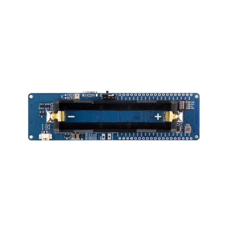
  • Multi-Source Power Management: Supports USB Type-C, 18650 lithium battery (holder included), and solar charging inputs with onboard charging, protection, and battery capacity measurement circuits.
  • Rich Peripheral Interfaces: Provides a 38-pin GPIO header, camera interface, USB switching IC with DIP selector, and a GNSS ceramic antenna for GPS/BeiDou/GLONASS positioning.
  • Complete Development Kit: Includes acrylic enclosure, speaker, FPC antenna, pin headers, and cables for rapid prototyping of portable 4G WiFi hotspots, telemetry units, and smart monitoring systems.

Out of stock

Description

The Waveshare ESP32-S3 A7670E LTE 4G Development Board is engineered as a comprehensive edge computing platform for demanding IoT deployments requiring reliable cellular backhaul. Its architecture pairs the high-performance ESP32-S3R2 microcontroller, with integrated PSRAM and flash, with the A7670E-FASE cellular module, enabling seamless fallback between 4G Cat-1 (B1/B3/B5/B7/B8/B20) and 2G networks for data, voice, and SMS. The board’s sophisticated power subsystem manages multiple inputs—USB, single-cell Li-ion, or solar—and includes precise battery monitoring and low-power circuit control via DIP switches to optimize energy use in field deployments.

Designed for system integrators and developers, the board exposes a full suite of interfaces including a dedicated camera parallel port for the included OV2640 sensor, a TF card slot for expanded storage, and configurable USB channels for direct A7670E AT command debugging. The integrated multi-GNSS receiver with active ceramic antenna delivers accurate location data for asset tracking and mobile loggers. This convergence of processing, wireless connectivity, vision, and power management on a single board accelerates development of secure, standalone IoT nodes for industrial telemetry, remote surveillance, and mobile data acquisition systems.

Key Features

  • Dual-Core Wireless MCU: ESP32-S3R2 with 240MHz Xtensa LX7 cores, 512KB SRAM, 384KB ROM, 2MB PSRAM, and 16MB Flash for complex application logic.
  • 4G LTE Cat-1 & 2G Connectivity: Integrated A7670E module supports LTE-FDD bands (B1/B3/B5/B7/B8/B20) with uplink ≤5Mbps and downlink ≤10Mbps, plus GSM fallback for voice/SMS.
  • Integrated Vision & Storage: Onboard OV2640 camera (2MP) with parallel interface and microSD (TF) card slot for capturing and storing image data locally.
  • Advanced Power Architecture: Onboard switching charger supports USB and solar panel input for 18650 Li-ion cells, featuring battery protection, fuel gauging, and configurable power domain control.
  • Multi-GNSS Positioning: Built-in high-sensitivity GNSS receiver supporting GPS, BeiDou, and GLONASS constellations with a pre-installed active ceramic patch antenna.
  • Configurable Hardware Interfaces: DIP switches for camera power control, USB channel selection (ESP32 vs. A7670E), and peripheral power gating to minimize sleep current.
  • Comprehensive I/O Expansion: 38-pin GPIO header breaks out UART, I2C, SPI, ADC, DAC, and touch sensor lines for connecting sensors, displays, or industrial interfaces.
  • Development Ecosystem Support: Fully compatible with Arduino core for ESP32, ESP-IDF, and MicroPython, with extensive libraries for 4G, camera, and power management.

Applications

  • Remote Outdoor Monitoring: Deploy as a standalone, solar-powered surveillance node with 4G image upload and GNSS location tagging for construction sites or wildlife areas.
  • Portable 4G WiFi Hotspot/Gateway: Create a battery-operated mobile router for field teams, vehicles, or temporary pop-up connectivity using the ESP32's Wi-Fi AP mode.
  • Smart Agriculture & Environmental Sensing: Build distributed sensor stations measuring soil moisture, weather data, or crop health, transmitting aggregated data via LTE Cat-1.
  • Asset Tracking & Fleet Management: Develop compact GPS trackers with periodic location reporting over cellular networks, featuring low-power sleep modes between fixes.
  • Industrial IoT (IIoT) Telemetry: Interface with industrial sensors via RS485/Modbus (using external converter) to monitor equipment health and send alerts via 4G/SMS.

Technical Specifications

Microcontroller / SoCEspressif ESP32-S3R2 (Xtensa® LX7 Dual-Core, 240 MHz)
Wireless Protocols2.4 GHz Wi-Fi 4 (802.11 b/g/n), Bluetooth LE 5.0, 4G LTE Cat-1, 2G GSM
Cellular Frequency BandsLTE-FDD: B1 (2100), B3 (1800), B5 (850), B7 (2600), B8 (900), B20 (800)
Data Transmission Rate≤5 Mbps (Uplink), ≤10 Mbps (Downlink)
GNSS SupportGPS, BeiDou, GLONASS
Supply Voltage5V (USB Type-C / 5V Pin), 3.7V ~ 4.2V (18650 Battery / VBAT Pin)
Power Input SourcesUSB Type-C Port, 18650 Lithium Battery Holder, Solar Panel (via charging circuit)
Onboard CameraOV2640 (2 Megapixel) with Parallel Interface
Storage ExpansionMicroSD (TF) Card Slot
Key Interfaces38-pin GPIO Header, Camera FPC Connector, USB Type-C, USB Channel Switch, Speaker Output
Antenna ConnectorsIntegrated GNSS Ceramic Antenna, u.FL/IPEX for 4G FPC Antenna (included)
Operating TemperatureCommercial Grade (implied, typical for ESP32/A7670E)
Dimensions (Board)Approx. 16 cm x 12 cm (from shipping dimensions)

Frequently Asked Questions

How do I switch the USB port between programming the ESP32-S3 and debugging the A7670E 4G module?

Use the onboard DIP switch labeled for USB channel selection. One position routes the USB Type-C interface to the ESP32-S3's USB-to-serial bridge for firmware uploads via Arduino IDE or ESP-IDF. The other position connects it directly to the A7670E module's diagnostic port, allowing you to send AT commands from a PC terminal (e.g., using PuTTY or screen) to configure APN settings, check network registration, or send SMS. Always power cycle the board after changing the switch position.

What is the procedure for setting up the 4G internet connection and creating a portable WiFi hotspot with this board?

First, ensure a valid SIM card is inserted and the board is powered via USB or a charged 18650 battery. Use the USB switch to connect to the A7670E and send AT commands (e.g., AT+CGDCONT=1,"IP","yourAPN") to configure the carrier APN. Then, switch back to ESP32 mode and upload a sketch that initializes the A7670E via its hardware UART, enables network attachment, and starts the ESP32's Wi-Fi in SoftAP mode. The board will then share its 4G connection as a WiFi network. Example code is provided in the Waveshare resources.

Can I power this development board solely from a solar panel, and what are the specifications for the solar input?

Yes, the board includes a solar charging circuit. You can connect a solar panel (typically 5V to 6V open-circuit voltage, with a recommended power of 5W or less) directly to the dedicated solar input terminals. The onboard switching charger (IP5306) will manage the charging of an attached 18650 lithium battery, providing power path management to run the system simultaneously. For optimal performance, ensure the panel's voltage does not exceed 6V to avoid damaging the charger IC, and use a diode in series if your panel lacks built-in reverse current protection.

How do I access and capture images from the onboard OV2640 camera using the Arduino IDE?

Install the ESP32 board package in Arduino IDE and include relevant libraries like 'esp32-camera' from Espressif. In your sketch, configure the camera pins (defined in the board's pinout diagram) and initialize the sensor with desired resolution (e.g., UXGA, SVGA). The image data can be captured to a buffer, then processed locally for edge AI, saved to the microSD card using the SD library, or transmitted over 4G via HTTP/MQTT. The DIP switch for camera power must be in the 'ON' position. Refer to the provided examples for complete wiring and configuration code.

Package Includes

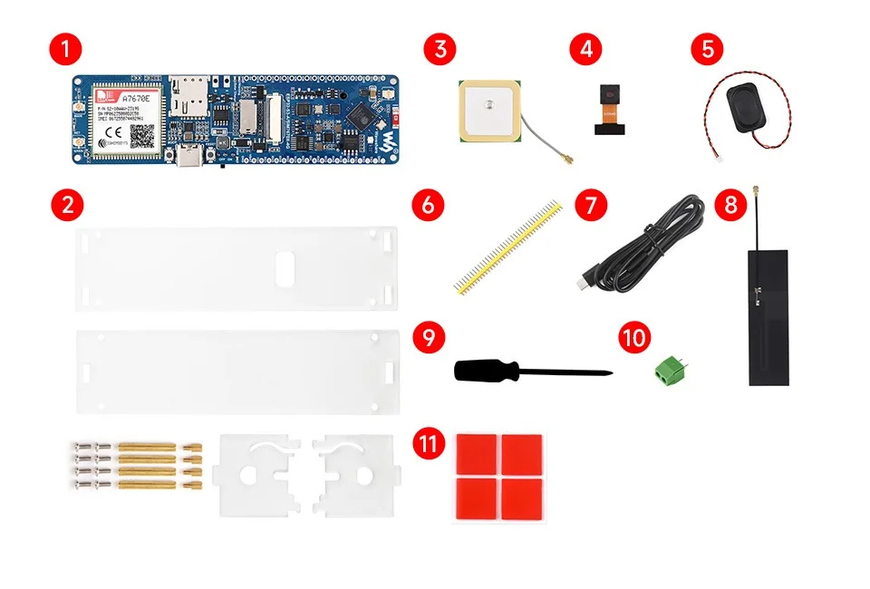
  • 1 x ESP32-S3-A7670E-4G Development Board
  • 1 x Transparent Acrylic Case and Screws Pack
  • 1 x GNSS Ceramic Antenna
  • 1 x OV2640 Camera Module
  • 1 x 8Ω 2W 2030 Mini Speaker
  • 1 x 40-Pin Yellow Straight Pin Header
  • 1 x USB Type-A to Type-C Cable (1m)
  • 1 x FPC Antenna (for 4G)
  • 1 x Screwdriver
  • 1 x 2-Pin Screw Terminal
  • 4 x Double-Sided Tape Pads

Additional Information

Weight 0.17 kg
Dimensions 16 × 12 × 5 cm